Quick release removable bridge caliper

a bridge caliper and quick release technology, applied in the direction of axially engaging brakes, brake types, braking elements, etc., can solve the problems of requiring periodic replacement of brake pads, friction elements, and significant effort in the removal of the entire caliper assembly, and reducing the service life of brake pads

Inactive Publication Date: 2008-10-21
PERFORMANCE FRICTION
View PDF24 Cites 35 Cited by
  • Summary
  • Abstract
  • Description
  • Claims
  • Application Information

AI Technical Summary

Benefits of technology

[0013]Another aspect of embodiments of the invention is to provide a caliper assembly that offers stiffness, particularly with respect to the brake pad supporting bridge.

Problems solved by technology

The brake pads, which include friction elements, require periodic replacement due to wear.
However, as can be appreciated, removal of the entire caliper assembly requires significant effort.
Removal and replacement is still complicated as multiple bolts must be removed and reinstalled during replacement, but the change time is less than removing the entire caliper assembly in the integral bridge design.
The spring clamp holds the pads in vertically, similar to the integral and bolted bridges, but does not offer the stiffness of the integral and bolted bridges.

Method used


Image

  • Quick release removable bridge caliper
  • Quick release removable bridge caliper
  • Quick release removable bridge caliper

Examples


Embodiment Construction

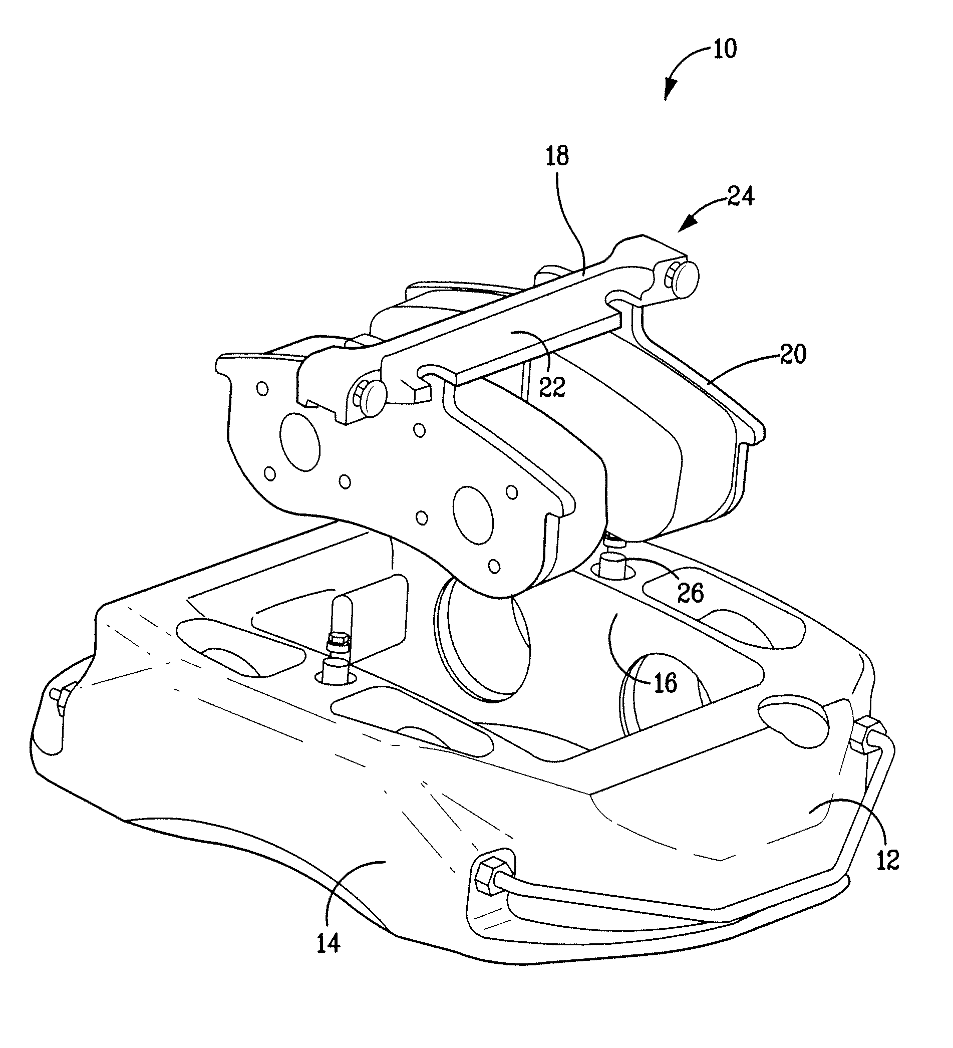
[0030]This invention is described for use in a vehicular disc brake system. The caliper described below is used for illustrative purposes only and it will be understood that this invention may be used in various types of braking systems and with any rotor.

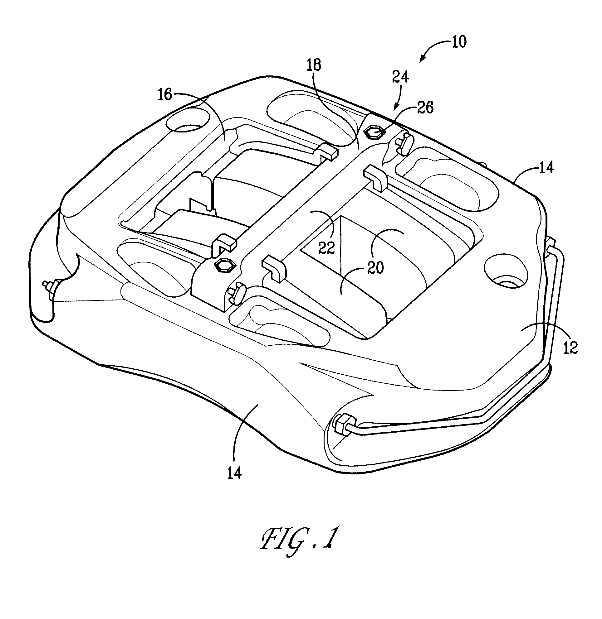
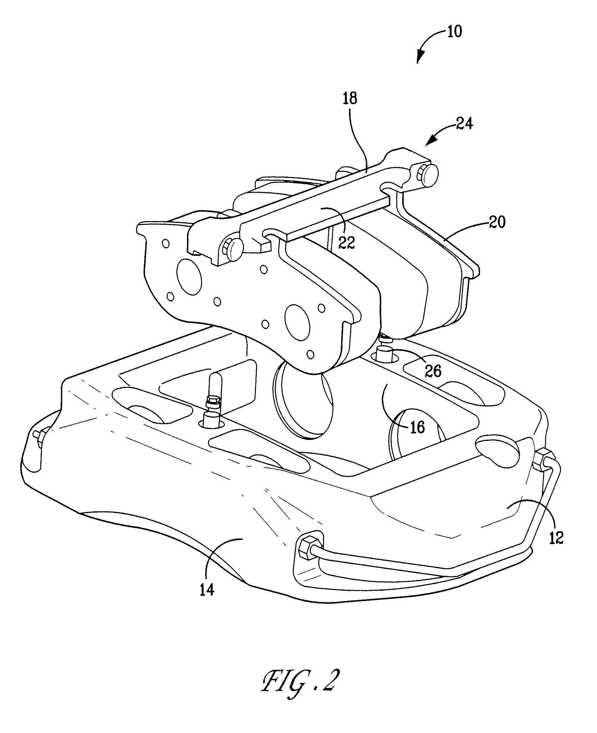
[0031]Referring to FIGS. 1 and 2, a brake caliper assembly 10 includes a caliper body 12 that has side portions 14 and a central opening 16. A bridge 18 is releasably connected to the top of the caliper body 12. Brake pads 20, which are formed by friction material carried on a backing plate, are slidably mounted on the longitudinal sides 22 of the bridge 18. The sides 22 act as rails that the brake pads slide on to selectively clamp a brake rotor disc, as is known. The brake pads 20 are designed to move toward each other by pistons, not shown, to press on the rotor to effect braking of a vehicle. The bridge 18 is releasably connected to the caliper body 12 by a spring loaded latch assembly 24, described in detail below.

[0032]As see...


PUM


Abstract

A brake caliper has a removable bridge that acts as a rigid mount for a pair of brake pad holders. The removable bridge is retained on the caliper body by spring loaded push button that allows quick removal for replacement of the brake pads, which is especially suited for automotive racing situations. The bridge is snapped in place and rigidly retained on caliper body when in use.

Description

RELATED APPLICATIONS[0001]This application claims priority under 35 U.S.C. §119(e) to provisional application No. 60 / 610,543 filed Sep. 17, 2004. The contents of this priority application are incorporated herein by reference.BACKGROUND OF THE INVENTION[0002]1. Field of the Invention[0003]This invention relates to brake calipers for use with disc brakes.[0004]2. Discussion of Related Art[0005]In typical disc brake assemblies, a rotor is mounted on a wheel hub for rotation. One or more pairs of brake pads, generally designed as friction material carried on a backing plate, are supported on either side of the rotor by a caliper or an anchor bracket. Calipers are designed to apply the braking force by moving a piston relative to the rotor to thereby move the brake pad into and out of contact with the rotor. The pistons are supported in a bore and abut the backing plate of the brake pad to move the brake pad toward the rotor upon application of a braking force. The caliper can be hydraul...

Claims


Application Information

Patent Timeline
Patent Type & Authority Patents(United States)
IPC IPC(8): F16D55/00
CPCF16D65/0043
Inventor BURGOON, DONALDDONG, DARRICKROBERTSON, GRAFTONQIAN, WENQI
Owner PERFORMANCE FRICTION
Why Eureka
Try Eureka