Knee cosmesis

a knee joint and cosmesis technology, applied in the field of prosthetic devices, can solve the problems of endoskeleton components, the need to destroy foam-in-place materials,

Inactive Publication Date: 2008-10-21
PROSTHETIC DESIGN
View PDF15 Cites 11 Cited by
  • Summary
  • Abstract
  • Description
  • Claims
  • Application Information

AI Technical Summary

Problems solved by technology

A cosmesis made in this manner has a drawback that the foam-in-place material must be usually destroyed if the endoskeletal components, which may include hydraulic units, control units, sockets, interconnection components, etc., require adjustment, replacement, and / or service in any respect.

Method used


Image

  • Knee cosmesis
  • Knee cosmesis
  • Knee cosmesis

Examples


Embodiment Construction

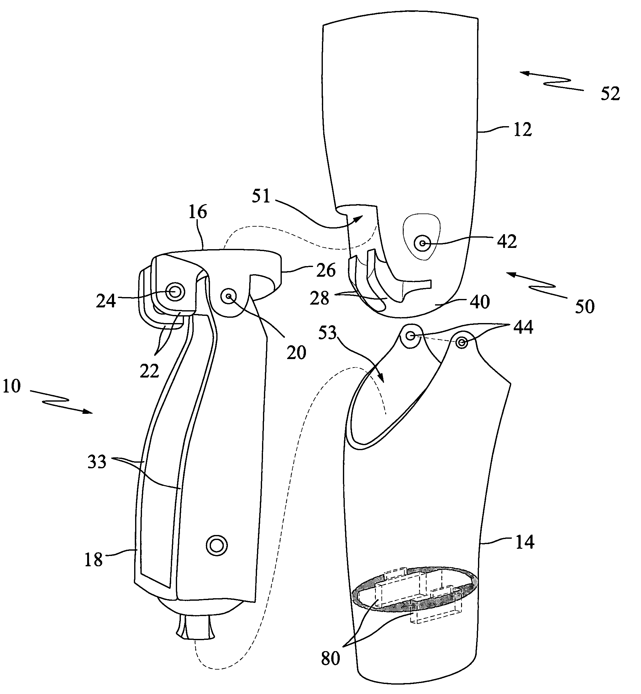
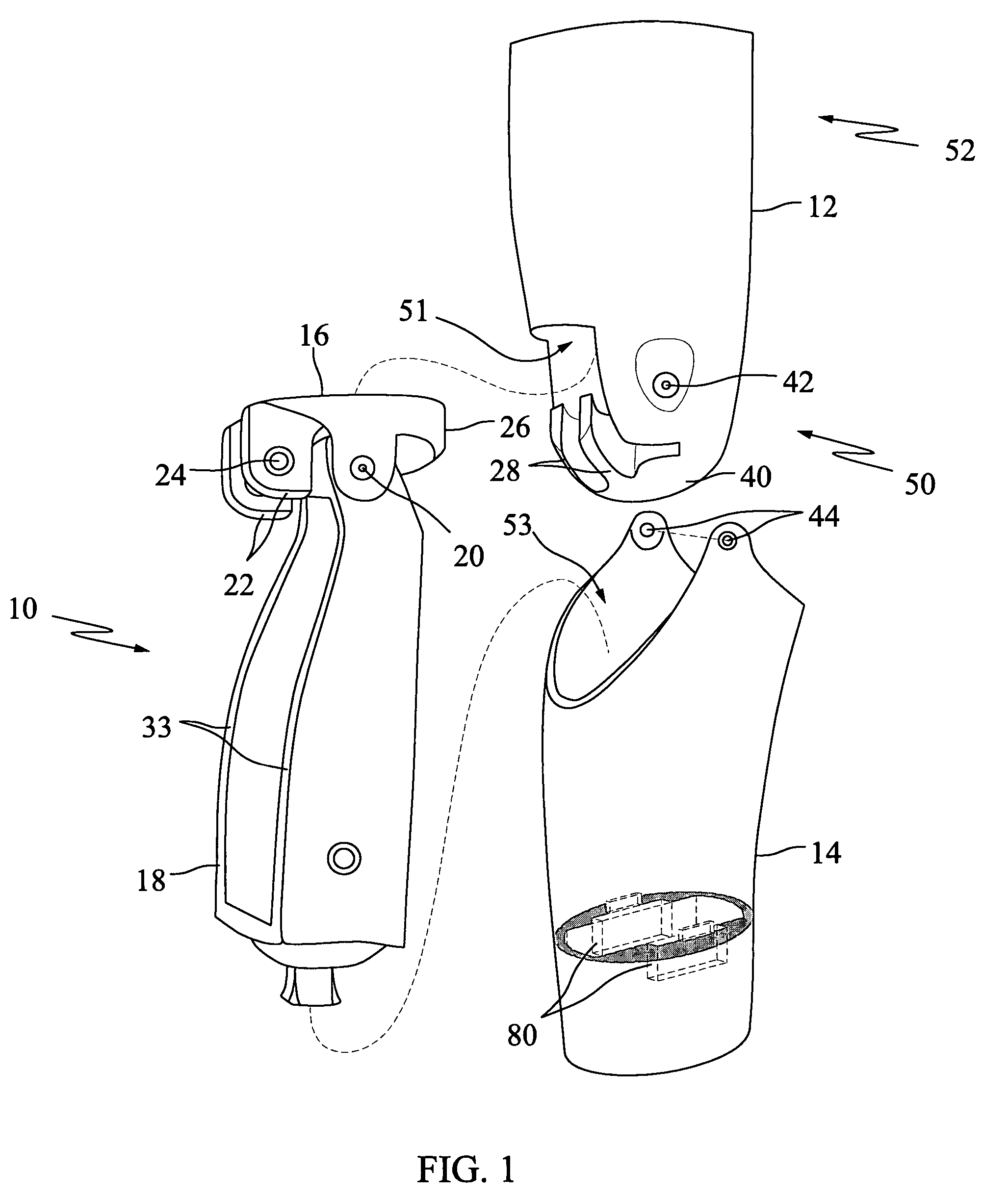
[0017]The exemplary embodiments of present invention provide a cosmesis for a prosthetic knee joint. In an exemplary embodiment, the prosthetic knee joint has the form described in co-pending U.S. Patent Application Publication Number 2004 / 0059433, the disclosure of which is incorporated herein by reference. But it will be apparent to persons of ordinary skill in the art that other types of prosthetic knee joints can be used as well.

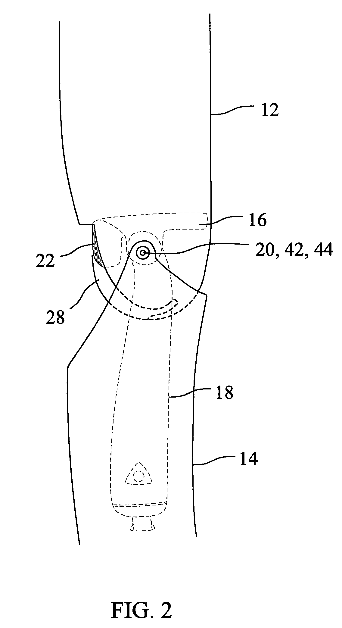
[0018]FIG. 1 is an exploded view showing the prosthetic knee joint 10 and a two-part cosmesis, according to an exemplary embodiment of the present invention. The cosmesis generally includes a tubular or conical thigh component 12 and a tubular shin component 14. The knee joint 10 (also called an endoskeletal knee chassis) includes a proximal segment 16 and a distal segment 18. The proximal segment 16 is pivotally coupled to the distal segment 18 by a hinge assembly 20. The proximal segment 16 includes posterior projections 22 having holes 24 extending th...


PUM


Abstract

A cosmesis includes a thigh component and a shin component that fit over a prosthetic knee joint. The thigh component and shin component are pivotally joined along an axis of rotation coinciding with that of the prosthetic knee joint. The thigh component and shin component can include internal contours molded into their inside walls to seat the prosthetic knee joint securely therein. The knee ball region of the thigh component can be made relatively thicker to provide a protective cushion and allow the patient to kneel. Additionally, a floating knee cap can be fit over the knee ball area. The upper end of the thigh component can be made of sufficiently thin material to permit rolling onto itself.

Description

BACKGROUND OF THE INVENTION[0001]This invention relates to prosthetic devices, and specifically to a cosmesis for covering a prosthetic knee joint.[0002]Prosthetic devices, such as prosthetic limbs, can be fitted with a cosmetic covering, sometimes called a cosmesis, that is designed to approximate the visual appearance of a human limb. One technique for fabricating such a cosmesis contemplates an encapsulation of the endoskeletal components of the prosthetic limb with a matrix substance (i.e. rigid foam) formed from a liquid resin containing a blowing agent which by / through application and control of appropriate conditions creates a foamed-in-place matrix, mass, or body, which is thereafter processed (i.e. milled and / or ground) by appropriate tooling and finishing to approximate the appearance / contour of the limb replaced. In a variant approach, a form or enclosure is positioned about the endoskeletal components as to define a cavity; and thence, there is introduced thereto, a volu...

Claims


Application Information

Patent Timeline
Patent Type & Authority Patents(United States)
IPC IPC(8): A61F2/60
CPCA61F2/64A61F2002/5001A61F2002/648A61F2002/745A61F2002/747A61F2/74
Inventor SLEMKER, TRACY C.
Owner PROSTHETIC DESIGN
Why Eureka
Try Eureka