Bipedal Exoskeleton and Methods of Use

Inactive Publication Date: 2014-04-10
CRAIG TRAVIS +5
View PDF10 Cites 90 Cited by
  • Summary
  • Abstract
  • Description
  • Claims
  • Application Information

AI Technical Summary

Problems solved by technology

However, most such devices also have some means to transmit loads to the wearer's hips and trunk.

Method used


Image

  • Bipedal Exoskeleton and Methods of Use
  • Bipedal Exoskeleton and Methods of Use
  • Bipedal Exoskeleton and Methods of Use

Examples


Embodiment Construction

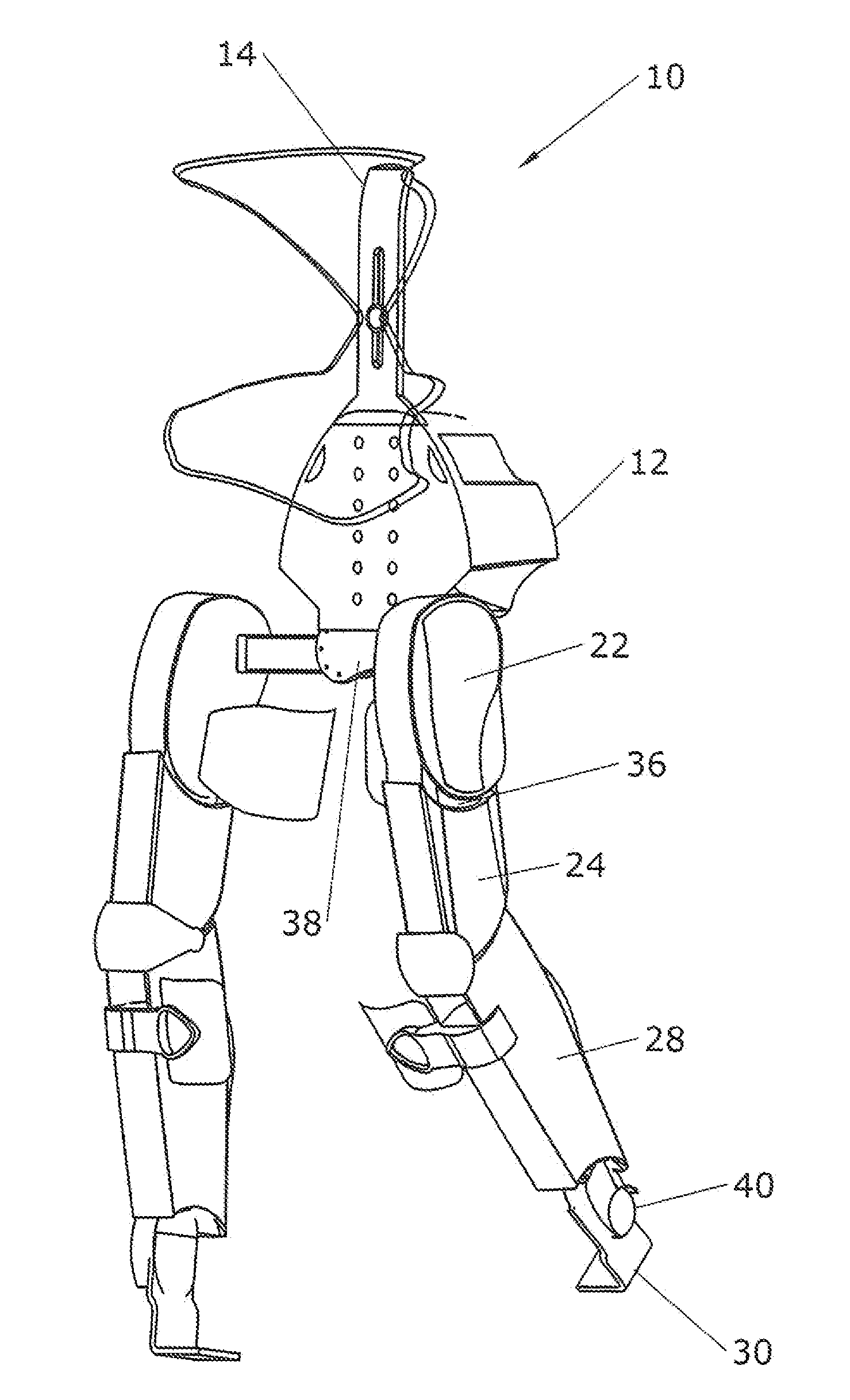
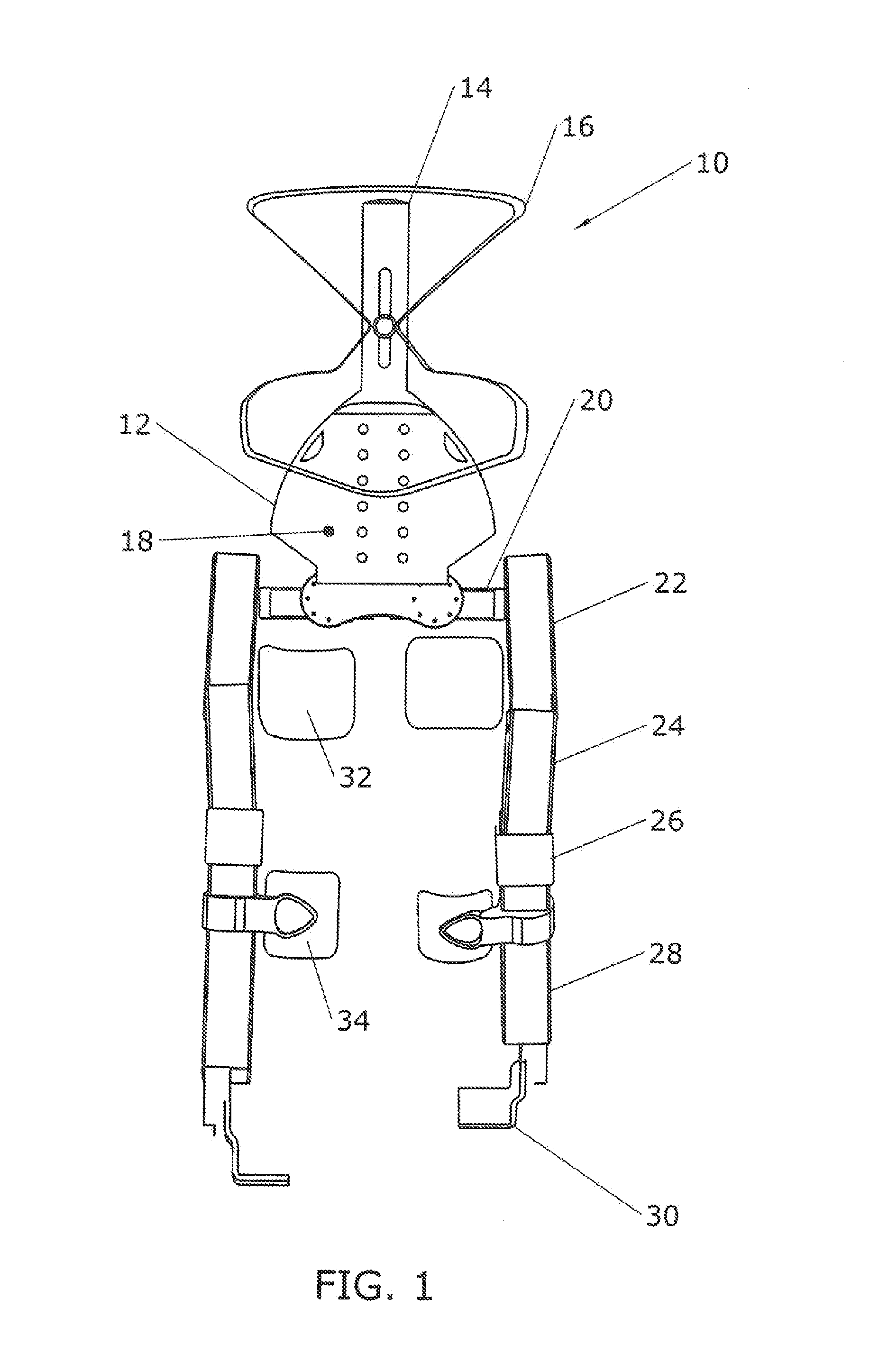
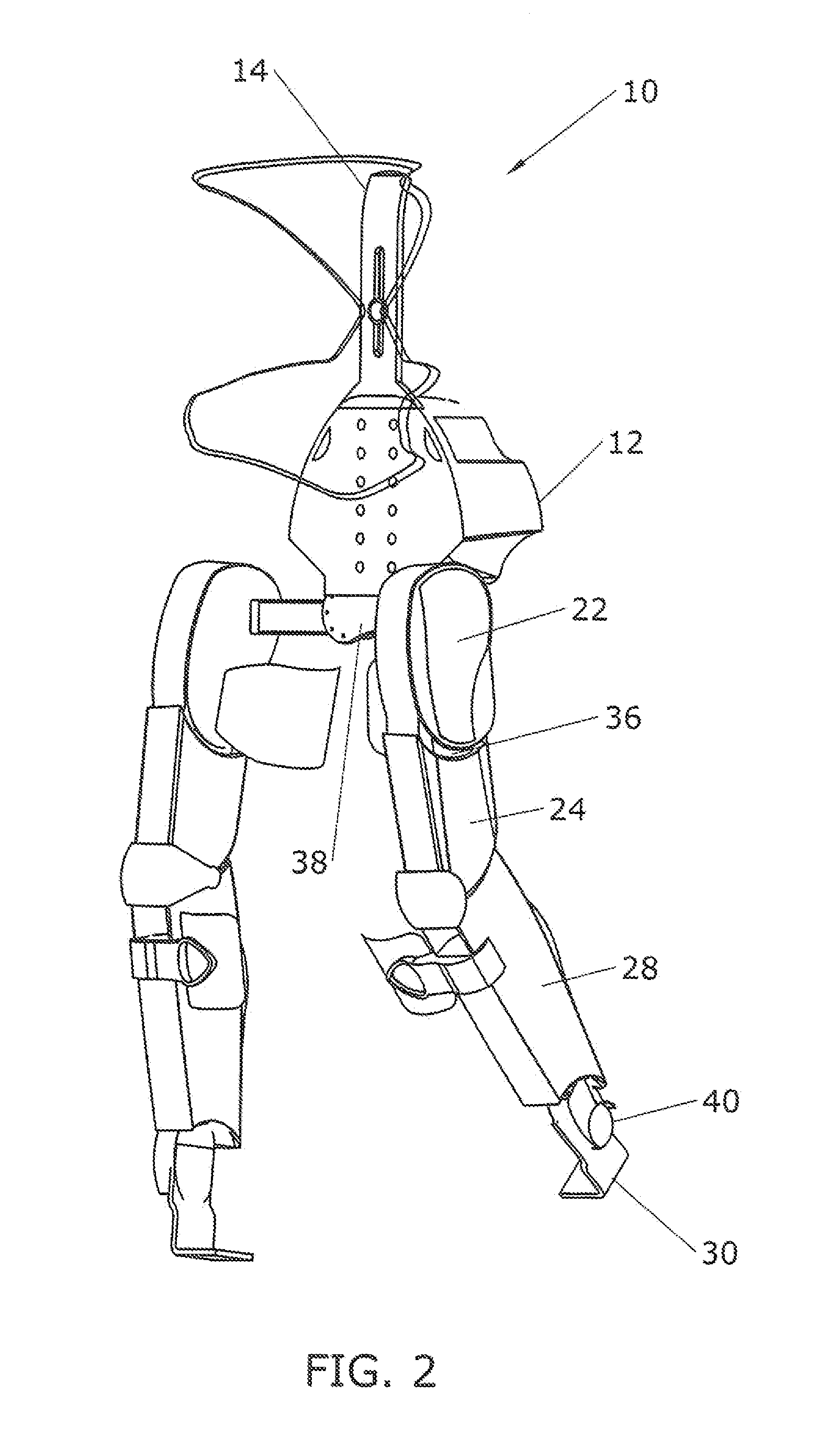
[0025]FIG. 1 shows a front elevation view of exoskeleton 10 made according to the present invention. FIG. 2 shows a right front perspective view of the exoskeleton in the same configuration. The exoskeleton is designed to be worn by a human user. Its two legs operate in parallel with the normal range of motion of the user's legs. The exoskeleton legs lie on the lateral outward side of each leg of the operator.

[0026]The two legs are attached to chassis 38. Housing 12 is also connected to chassis 38. The housing preferably contains one or more central processing units (“CPU”) running software that controls the functions of the exoskeleton. Sensors are provided so that the control can be closed-loop. For instance, sensors may be provided to determine the position of each joint in the exoskeleton and the force applied to the joint. The CPU uses this formation to control the motion of the joints.

[0027]Returning not to FIG. 1, the basic components of a preferred embodiment of the exoskele...


PUM


Abstract

A bipedal exoskeleton configured to be worn by a human user. The exoskeleton includes a soft “backpack”-style harness that interfaces primarily with the user's waist, back, and shoulders. A chassis is provided to mount two positively-driven legs. Each leg includes features that are analogous to a human leg—a hip joint, a thigh, a knee joint, a calf, and a foot plate. Each leg of the exoskeleton is physically connected to one of the human user's legs. A thigh cuff is used to connect to the user's thigh. A shin cuff is used to connect to the user's calf. A foot plate rests beneath the sole of the user's foot. Power actuators are provided in the exoskeleton's hip and knee joints, and possibly additional locations. A user interface is provided in one or more locations so that the user can control desired functions of the exoskeleton.

Description

CROSS-REFERENCES TO RELATED APPLICATIONS[0001]This non-provisional patent application claims the benefit of an earlier-filed provisional patent application. The provisional application was assigned Ser. No. 61 / 709,489. It was filed on Oct. 4, 2012.STATEMENT REGARDING FEDERALLY SPONSORED RESEARCH OR DEVELOPMENT[0002]This invention was funded at least in part under a National Aeronautics and Space Administration contract and is subject to 35 U.S.C. section 200 et. seq. At least a portion of the invention was also made in the performance of work under a NASA contract and is subject to the provisions of Section 305 of the National Aeronautics and Space Act of 1958, Public Law 85-568 (now 51 U.S.C. §20135). At least one of the named inventors was employee of the United States Government at the time the invention was made and the United States thereby obtained certain rights of use of the invention without the payment of any royalties.MICROFICHE APPENDIX[0003]Not Applicable memberBACKGROU...

Claims


Application Information

Patent Timeline
Patent Type & Authority Applications(United States)
IPC IPC(8): A61H3/00B25J9/00
CPCB25J9/0006A61H3/00A61H1/024A61H1/0244A61H2201/1215A61H2201/165A61H2201/1671A61H2201/5002A61H2201/5007A61H2201/5038A61H2201/5046A61H2201/5061A61H2201/5064A61H2201/5079A61H2201/5084A61H2201/5097
Inventor CRAIG, TRAVISKOVEKAMP, ROGERNEUHAUS, PETERNOORDEN, JERRYLLPAYTON, NICRADFORD, NIC
Owner CRAIG TRAVIS
Why Eureka
Try Eureka