Fixing of a brake-fluid reservoir

a technology of brake fluid and fixing rod, which is applied in the field of reservoirs, can solve the problems of immobilizing the mounting element, fitting and removing the reservoir, and requiring tools and a certain amount of time, and achieves the effect of convenient fitting and removal of the reservoir

Active Publication Date: 2008-10-28
ROBERT BOSCH GMBH
View PDF4 Cites 13 Cited by
  • Summary
  • Abstract
  • Description
  • Claims
  • Application Information

AI Technical Summary

Benefits of technology

[0005]The invention relates to a mounting system that facilitates the fitting and removing of the reservoir.

Problems solved by technology

However, these mounting elements must be immobilized using, for example, nuts for the bolts.
The fitting and removing of the reservoir therefore require tools and a certain amount of time.

Method used


Image

  • Fixing of a brake-fluid reservoir
  • Fixing of a brake-fluid reservoir
  • Fixing of a brake-fluid reservoir

Examples


Embodiment Construction

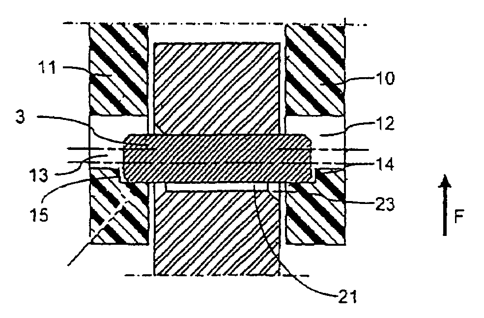
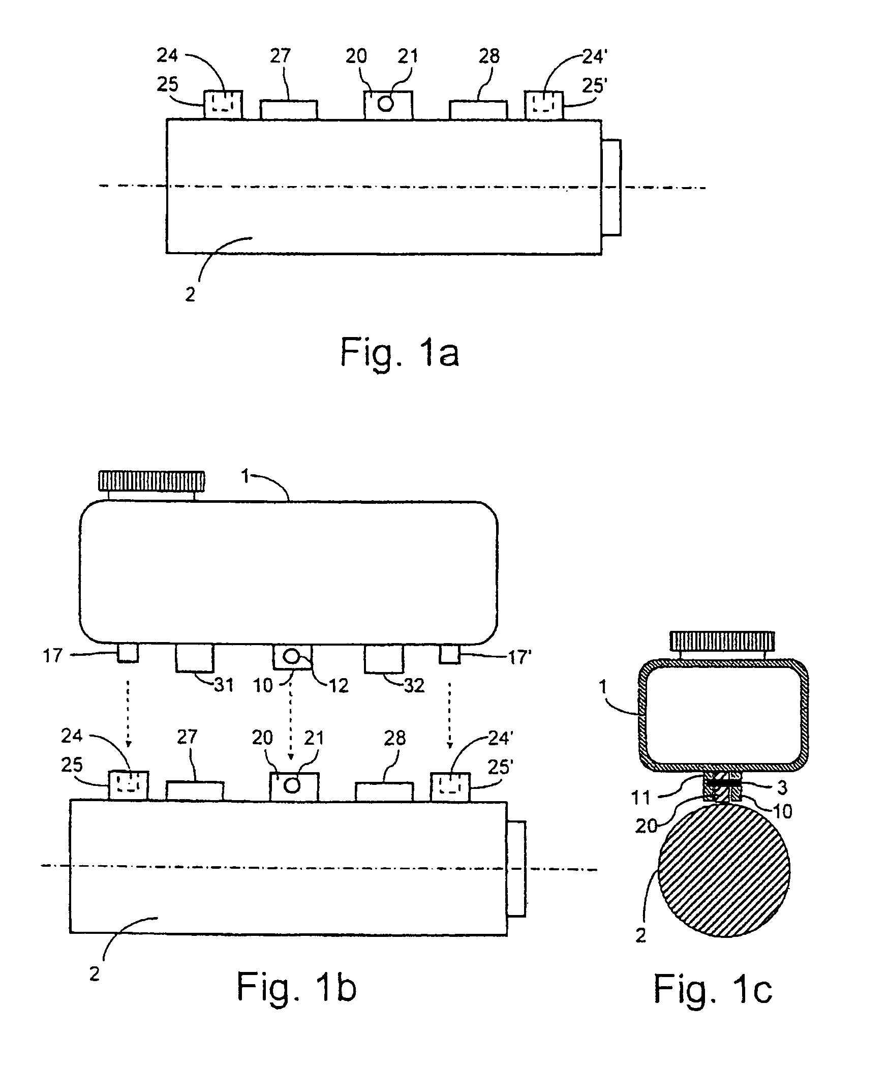
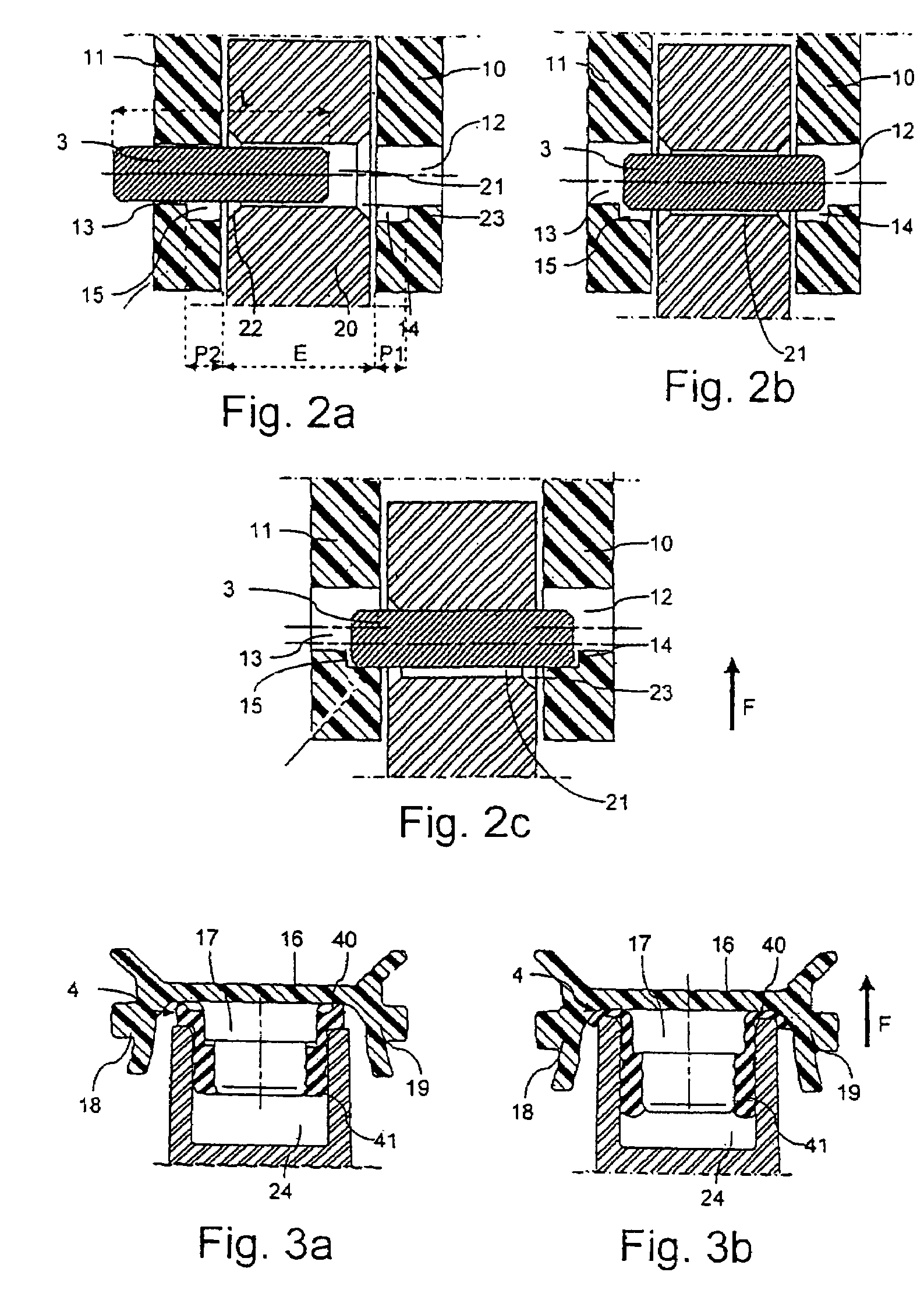
[0019]With reference to FIGS. 1a to 1c, a simplified embodiment according to the invention will first be described.

[0020]FIG. 1a illustrates a brake master cylinder allowing the invention to be used. This master cylinder 2 includes two inlets 27 and 28 for connecting with the inside of the master cylinder and introducing brake fluid with a view to filling the vehicle's hydraulic braking circuit. A mounting lug 20 including a hole 21 is provided in the upper portion of the master cylinder. Studs 25, 25′ including blind holes 24, 24′ are also provided, the use of which will be explained later.

[0021]The lower portion of FIG. 1b illustrates a brake master cylinder 2 such as the one in FIG. 1a and the upper portion of FIG. 1b illustrates a brake fluid reservoir 1 designed to be mounted on the master cylinder 2.

[0022]The reservoir 1 includes outlets 31 and 32 designed to be fitted into the inlets 27 and 28 of the brake master cylinder so as to connect the inside of the reservoir with the ...


PUM


Abstract

The invention relates to a brake fluid reservoir comprising at least two lateral mounting lugs (10, 11) designed to be placed either side of a central mounting lug (20) of a brake master cylinder. Collinear holes (12, 13, 21) traverse these lugs and are designed to receive a mounting pin (3). The said lugs include at least one device for the axial immobilization of the mounting pin (3).

Description

BACKGROUND OF THE INVENTION[0001]The invention relates to a reservoir and a system for mounting this reservoir on a support part. The invention is especially applicable to a brake fluid reservoir and the system for mounting it on a brake master cylinder.[0002]In a motor vehicle braking system, a brake fluid reservoir is mounted on the upper portion of a brake master cylinder in order to provide a reserve of fluid with a view to compensating for any reduction in the volume of fluid in the hydraulic braking circuit of the vehicle. The brake master cylinder is itself mounted on a braking assistance servo which is controlled by the brake pedal.[0003]There are various methods for mounting a reservoir on a brake master cylinder. In particular, some reservoirs are mounted using one or more mounting elements, such as pins or bolts, which pass through mounting lugs provided in the lower portion of the reservoir and mounting lugs which are provided on the upper portion of the brake master cyl...

Claims


Application Information

Patent Timeline
Patent Type & Authority Patents(United States)
IPC IPC(8): B60T11/26F15B7/08
CPCB60T11/22B60T17/06
Inventor BOURLON, PHILIPPEGRECH, DANIEL
Owner ROBERT BOSCH GMBH
Why Eureka
Try Eureka