Door lock device

a door lock and door lock technology, applied in the direction of passenger lock actuation, carpet fasteners, lock applications, etc., can solve the problems of unfavorable anti-theft ability

Inactive Publication Date: 2008-10-28
HONDA MOTOR CO LTD +1
View PDF24 Cites 24 Cited by
  • Summary
  • Abstract
  • Description
  • Claims
  • Application Information

AI Technical Summary

Problems solved by technology

This is unfavorable in respect of the antitheft ability.

Method used


Image

  • Door lock device
  • Door lock device
  • Door lock device

Examples


Embodiment Construction

[0031]Exemplary embodiments for a door lock device according to the present invention will be explained in detail with reference to the accompanying drawings. It is to be noted that the present invention is not restricted by these exemplary embodiments.

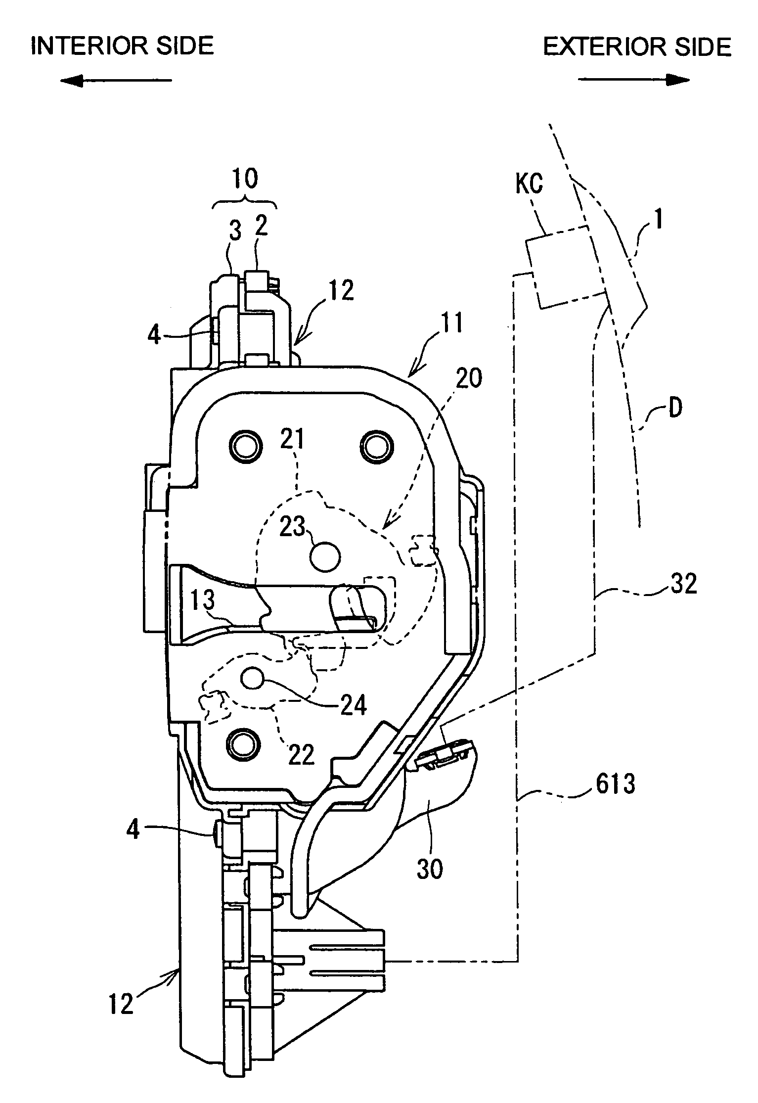
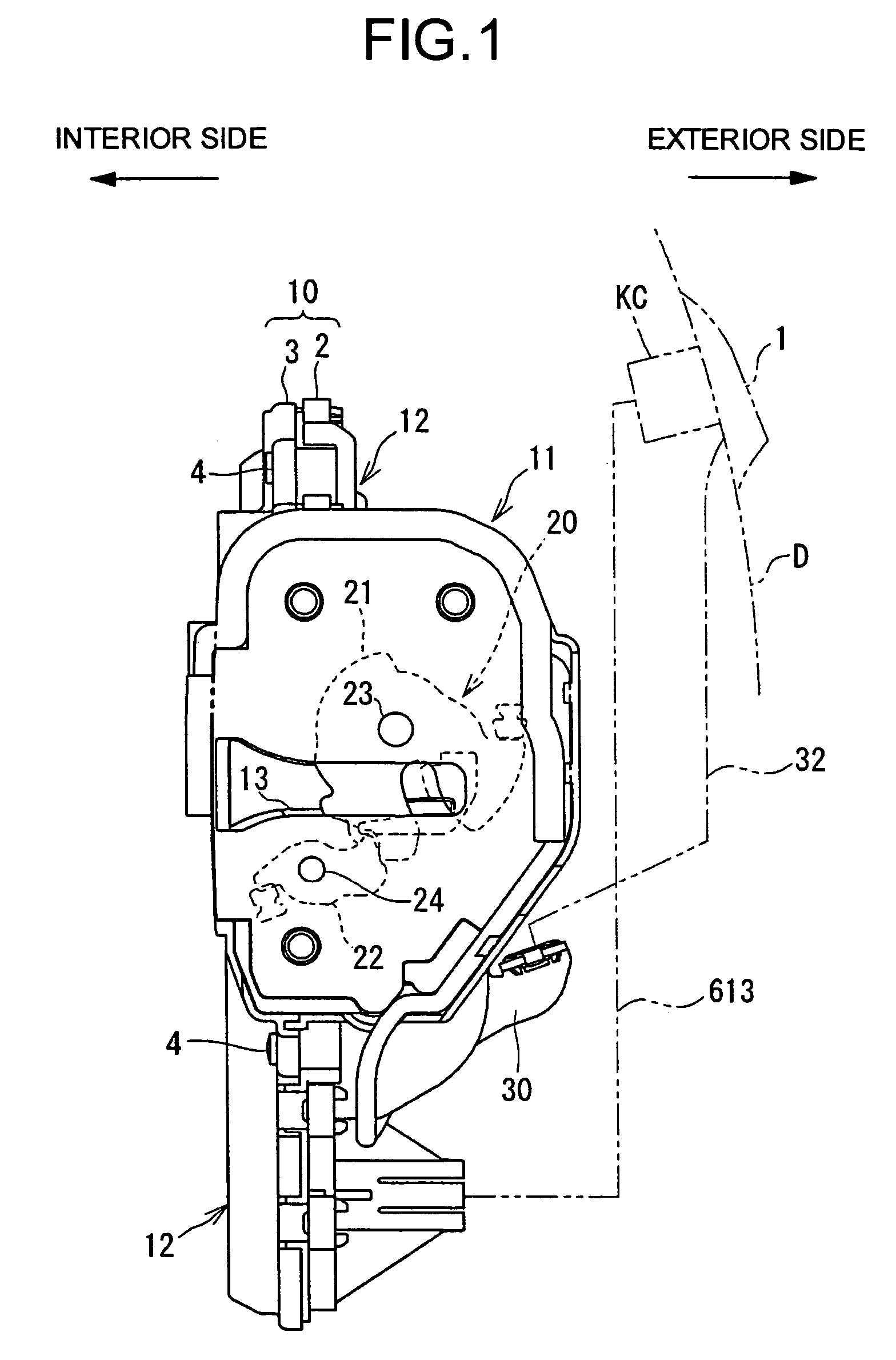
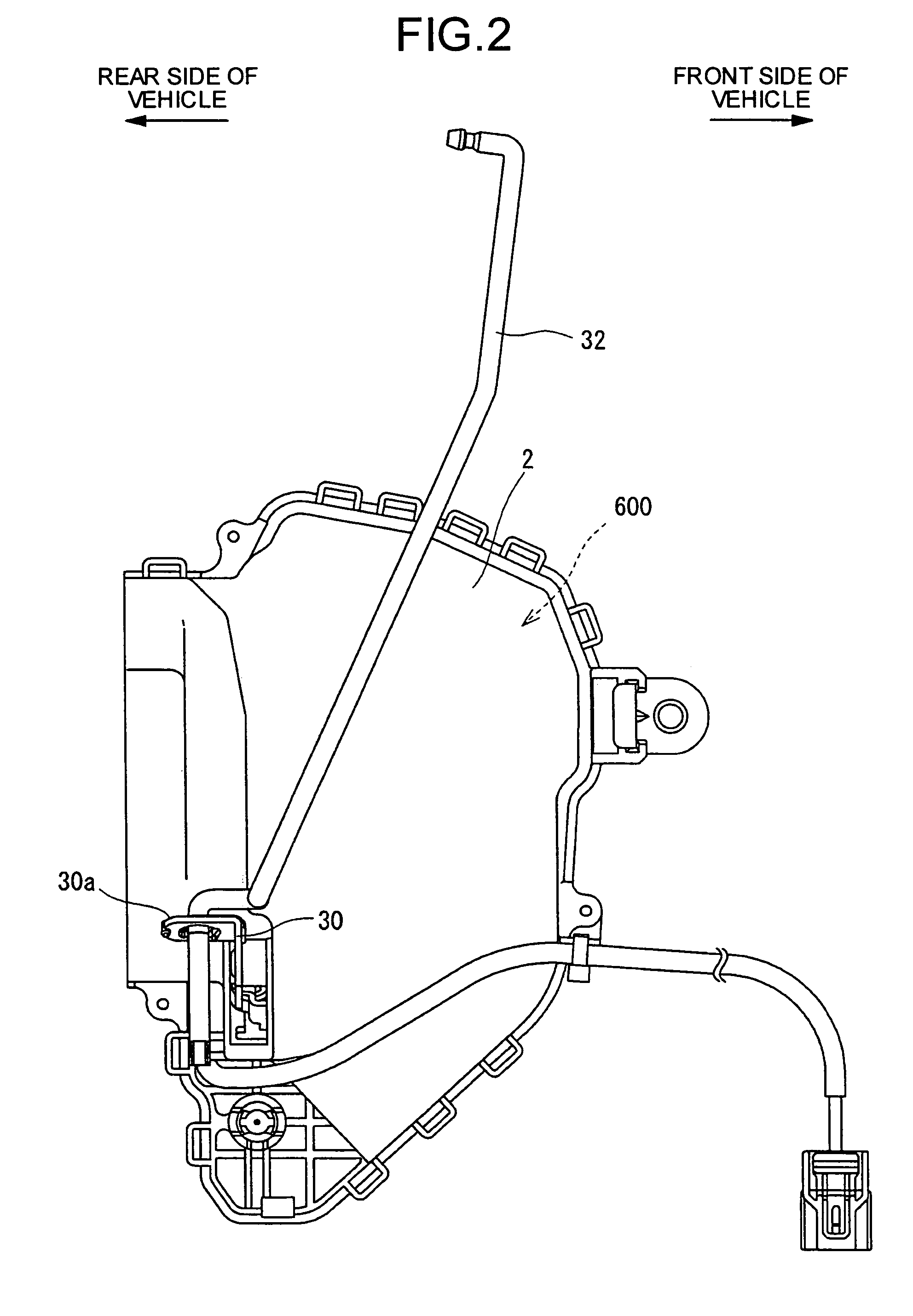
[0032]FIGS. 1 to 3 depict a door lock device which is an exemplary embodiment of the present invention. The door lock device illustrated herein is provided between an outside handle 1 and a latch mechanism 20 in a side door of front hinge type disposed on the right of front seat in a four-wheeled vehicle (door D on the side of the driving seat in the case of a right-hand-drive car), and includes a main casing 2 and a sub casing 3. These main casing 2 and sub casing 3 each formed of, for example, plastic are first joined with each other and then fastened with each other by a fastening unit 4 such as screw, thereby forming a housing 10. The joining surface between the main casing 2 and the sub casing 3 is intervened by an O-ring (not sh...


PUM


Abstract

When an inside lock button is operated for locking, an inner wire of a wire cable is drawn into an outer tube of the wire cable so that a lock lever shifts from an unlock state to a lock state, whereas when the inside lock button is operated for unlocking, the inner wire of the wire cable is pushed out of the outer tube of the wire cable so that the lock lever shifts from a lock state to an unlock state.

Description

BACKGROUND OF THE INVENTION[0001]1) Field of the Invention[0002]The present invention relates to a door lock device for a vehicle, and more particularly, to a door lock device that switches from an unlock state to a lock state of a door in response to an operation of an inside lock button.[0003]2) Description of the Related Art[0004]Conventionally, a vehicle, such as four-wheeled vehicle, generally has a door lock device provided between an outside handle disposed for a door and a latch mechanism. The latch mechanism usually has a latch and a ratchet, and is so configured that when a door is closed relative to the vehicle body, the latch hold a striker on the vehicle body side by meshing, and the ratchet keeps the meshing state between the latch and the striker, whereby the door is kept in closed state relative to the vehicle body. The door lock device has a lock mechanism which switches between an unlock state and a lock state in response to a key operation on a key cylinder provid...

Claims


Application Information

Patent Timeline
Patent Type & Authority Patents(United States)
IPC IPC(8): E05C3/06E05C3/16E05B53/00E05B65/12E05B65/20
CPCE05B81/06E05B79/20E05B81/16E05B81/34E05B81/66E05B77/16E05B77/30Y10S292/23Y10T292/1082Y10T292/1047
Inventor UMINO, MASAAKI
Owner HONDA MOTOR CO LTD
Why Eureka
Try Eureka