Single frame sling chair

a single frame and backrest technology, applied in the field of single frame sling chairs, can solve the problems of reducing the service life of the chair, so as to improve the service life, facilitate assembly, and facilitate the effect of assembly

Active Publication Date: 2008-12-02
AGIO INT
View PDF21 Cites 4 Cited by
  • Summary
  • Abstract
  • Description
  • Claims
  • Application Information

AI Technical Summary

Benefits of technology

[0003]The present invention provides a connection assembly for a sling chair which allows for efficient chair assembly and results in a comfortable yet sturdy chair. The present invention includes a back frame member having side rails held in substantially parallel relation by a pair of cross bar members. In one embodiment, the cross bar members are generally curved so as to extend away from the back faces of the side rails, forming a concave back structure which can receive a sling member and, eventually, a seated occupant. The cross bar members are adapted to retain the sling member in secure fashion through upper and lower backrest assemblies. In this way, the sling member is not secured to the side rails, but rather to the cross bar members, resulting in better support, a more secure connection and more efficient assembly. The method of securing the sling member using a detachable support bar having a scaffold support element ensures that the sling member is efficiently and securely retained. The present invention also facilitates separate provisioning of decorative features to improve the chair's aesthetic qualities.

Problems solved by technology

Different mechanisms have been employed for securing the backrest to the back frame, and these prior art mechanisms have suffered from several deficiencies.
First, these prior art mechanisms often fail to provide a secure connection, which can result in the backrest being unsupportive of the seated individual.
Further, the sling backrest for these chairs is frequently retained along the chair side rail supports, creating side-to-side sling tension, restricting the potential to add decorative chair features, and complicating assembly.

Method used


Image

  • Single frame sling chair
  • Single frame sling chair
  • Single frame sling chair

Examples


Embodiment Construction

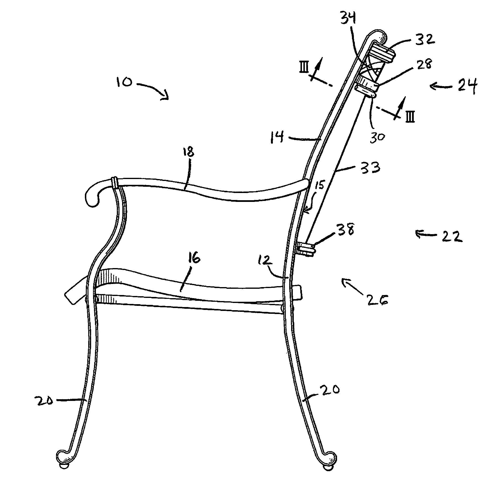
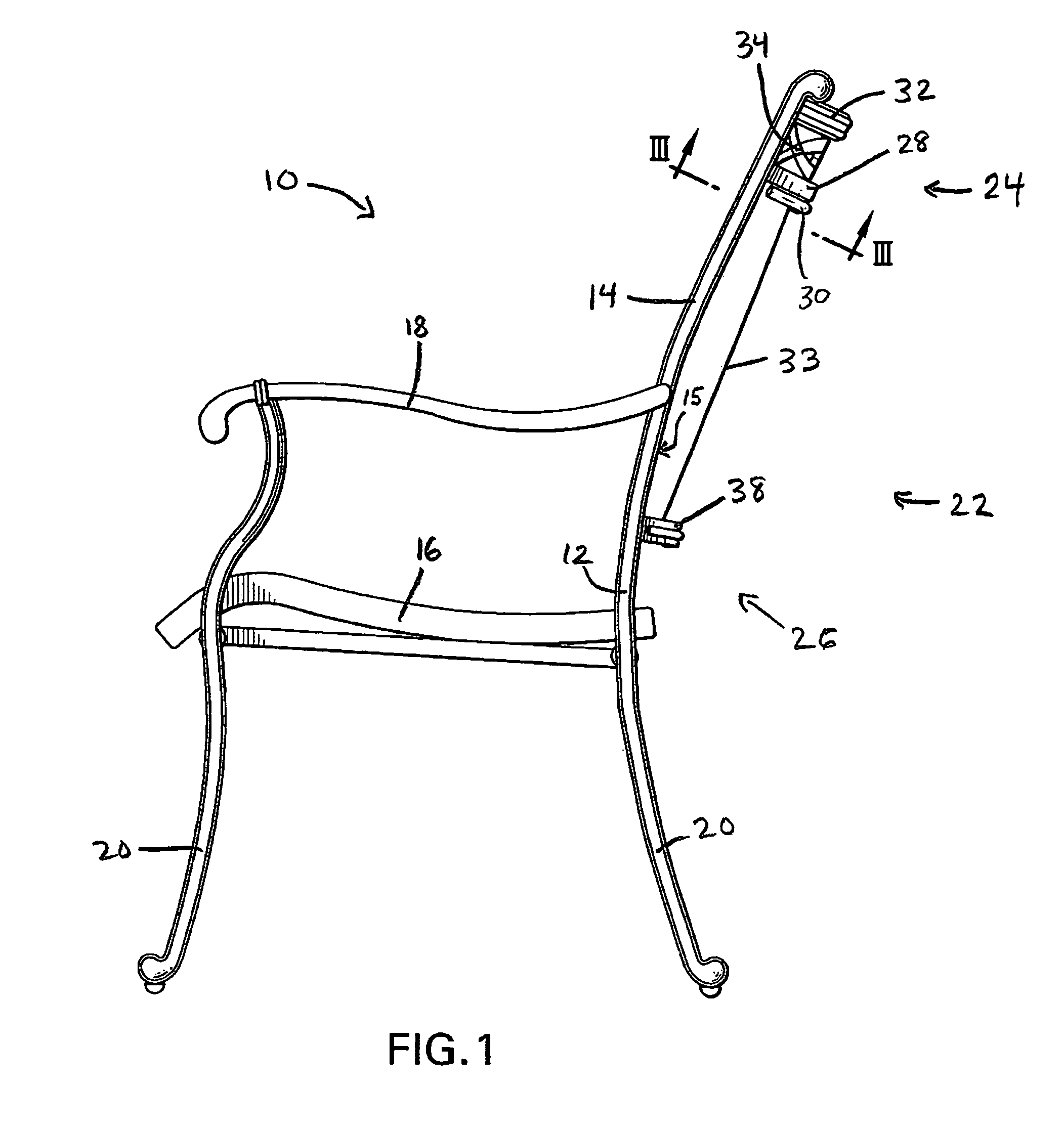
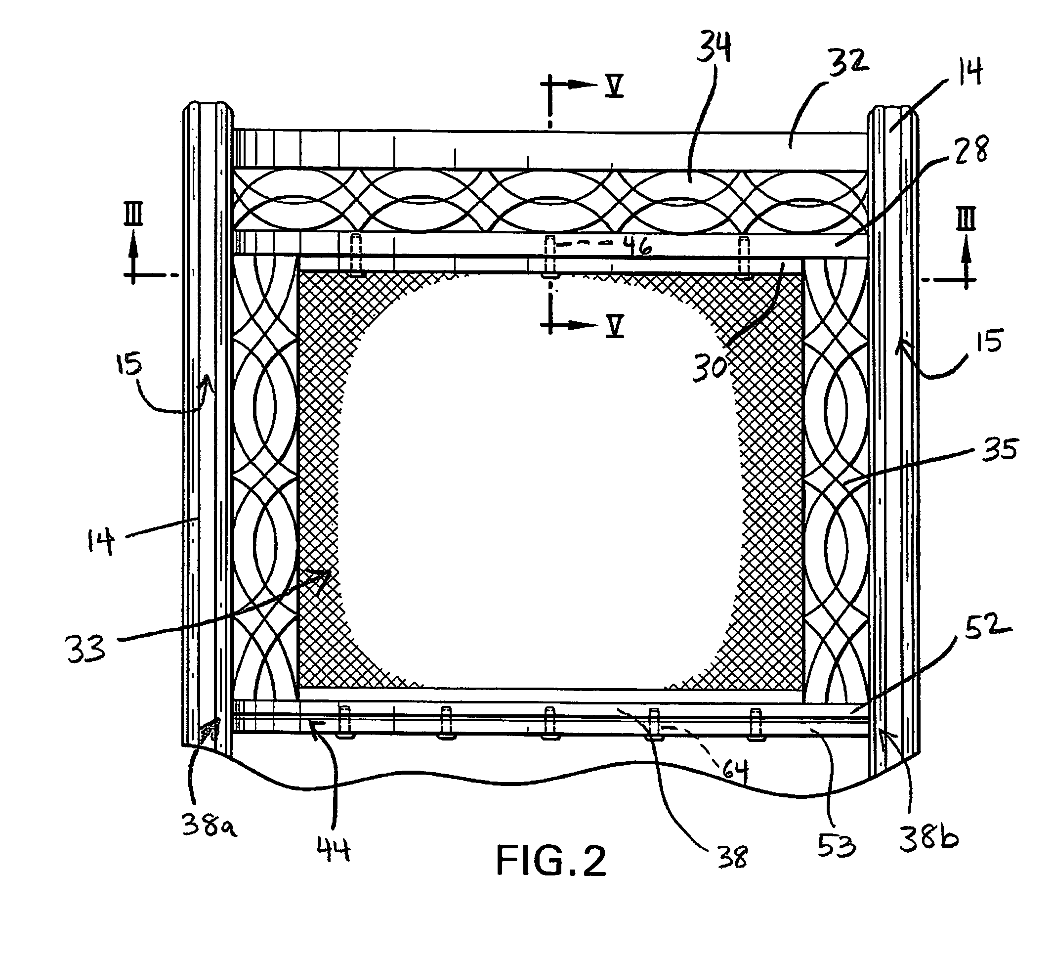
[0010]As shown in FIGS. 1 through 6, the present invention provides a single frame sling chair 10, having a rigid frame 12. FIG. 1 shows an overall, right side view of one embodiment of a chair according to the present invention, including monolithic welded frame 12 comprising frame rails 14, seat 16, armrests 18 and leg portions 20. A backrest assembly 22 is also shown, including upper backrest assembly portion 24 and lower backrest assembly portion 26. Upper backrest assembly portion 22 includes top cross bar 28 and detachable support bar 30, described more completely hereafter. Top cross bar 28 may be integrally formed with top element 32 and connective fascia 34, or may be secured to elements 32 and 34 as separate members. Top cross bar is secured to, and acts as a spreader between, frame side rails 14, as shown in FIG. 2.

[0011]As further shown in FIGS. 1 and 2, lower backrest assembly portion 26 includes bottom cross bar 38 which is secured to frame rails 14 and acts as a sprea...


PUM


Abstract

A sling chair includes a back frame member having side rails held in substantially parallel relation by a pair of cross bar members. In one embodiment, the cross bar members are generally curved so as to extend away from the back faces of the side rails, forming a concave back structure which can receive a sling member and, eventually, a seated occupant. The cross bar members are adapted to retain the sling member in secure fashion through upper and lower backrest assemblies, resulting in better support and more efficient assembly. This also facilitates separate provisioning of decorative features to improve the chair's aesthetic qualities.

Description

FIELD OF THE INVENTION[0001]The present invention relates to chair constructions, and more particularly relates to a chair construction employing a sling-type backrest which promotes chair stability, comfort and a variety of design alternatives.BACKGROUND OF THE INVENTION[0002]Various types of sling chairs have been known which provide a somewhat concave and / or giving backrest. Such chairs generally include a back portion and a seat portion, and may optionally include armrest portions. The back portion generally includes a back frame and a flexible yet supportive backrest made of fabric or other suitable material and mounted to the back frame. Different mechanisms have been employed for securing the backrest to the back frame, and these prior art mechanisms have suffered from several deficiencies. First, these prior art mechanisms often fail to provide a secure connection, which can result in the backrest being unsupportive of the seated individual. Further, the sling backrest for t...

Claims


Application Information

Patent Timeline
Patent Type & Authority Patents(United States)
IPC IPC(8): A47C7/00A47C7/02
CPCA47C5/06A47C7/282A47C31/023
Inventor WANG, OLIVER
Owner AGIO INT
Why Eureka
Try Eureka