AI technical title is built by Patsnap AI team. It summarizes the technical point description of the patent document.
a biometric and multi-spectral imaging technology, applied in the field of biometrics, can solve the problems of poor image contrast, reduced image contrast, and easy to image quality problems
Active Publication Date: 2008-12-02
HID GLOBAL CORP
View PDF286 Cites 55 Cited by
Summary
Abstract
Description
Claims
Application Information
AI Technical Summary
This helps you quickly interpret patents by identifying the three key elements:
Problems solved by technology
Method used
Benefits of technology
Problems solved by technology
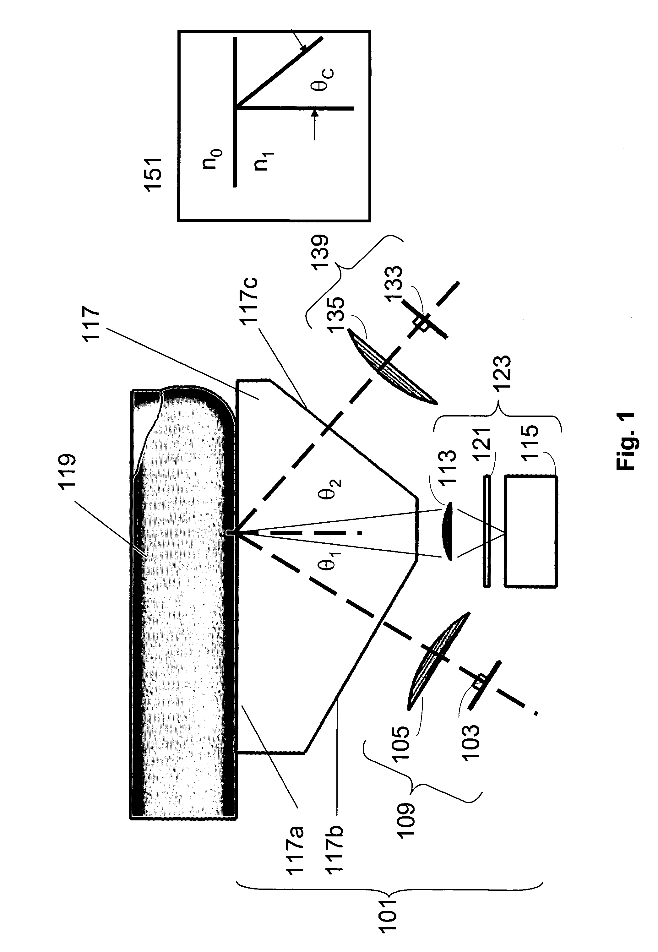
Alternatively, if skin of the proper index of refraction is in optical contact with the platen, the TIR at this location is “frustrated,” allowing light to traverse the platen-skin interface.
Although optical fingerprint readers based on TIR phenomena are one of the most commonly deployed types of fingerprint sensors, they are susceptible to image-quality problems due to non-ideal conditions.
If the skin is overly dry, the index match with the platen will be compromised, resulting in poor image contrast.
Similarly, if the finger is very wet, the valleys may fill with water, causing an optical coupling to occur all across the fingerprint region and greatly reduce image contrast.
These effects decrease image quality and thereby decrease the overall performance of the fingerprint sensor.
As a soft material, the membrane is subject to damage, wear, and contamination, limiting the use of the sensor before it requires maintenance.
Method used
Image
Click on the blue label to locate the original text in one second.
Reading with bidirectional positioning of images and text.
Examples
example
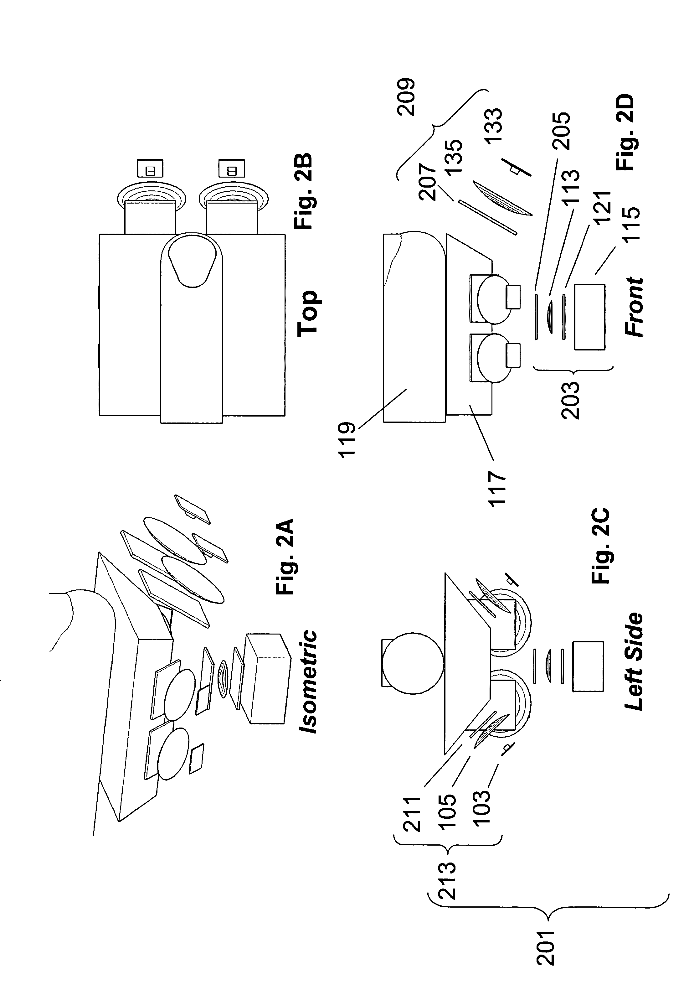
[0136]A specific example of a structure that incorporates a sensor as described herein for an embodiment is described in connection with FIGS. 15A-15D. In this embodiment, the sensor is comprised by a turnstile having the general structure shown in FIG. 15A, the turnstile being of the type that may be used to control access by people to different areas in an amusement park, sports arena, or the like. The different areas between which the turnstile controls access are denoted as a “paid area” and a “free area” in FIG. 15A. Access is controlled with a dropping-arm tripod obstacle 1502. The biometric sensor 1504 may be mounted on the top surface of the turnstile housing.
[0137]A specific structure for the biometric sensor is shown in FIG. 15B, with imaging taking place over a platen 1530 having an ergonomic cover plate; the back of the ergonomic cover plate may act as an optical reference. Direct illumination is provided by illumination sources 1534, some of which include polarizers and...
PUM
Abstract
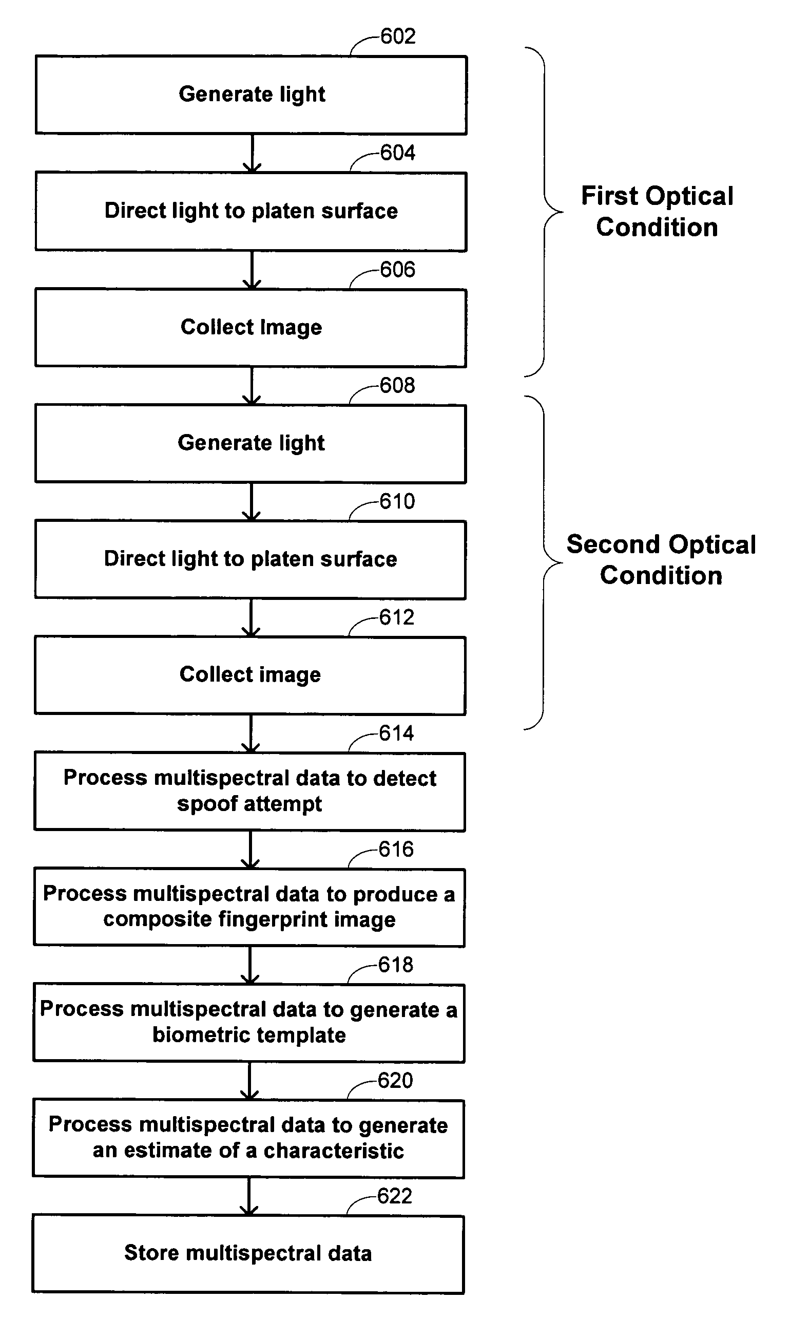
Methods and systems are provided for performing a biometric measurement on an individual. A purported skin site of the individual is illuminated under a plurality of distinct optical conditions during a single illumination session. Light scattered beneath a surface of the purported skin site is received separately for each of the plurality of distinct optical conditions. A multispectral image of the purported skin site is derived from the received light. A biometric function is performed with the derived multispectral image.
Description
CROSS-REFERENCES TO RELATED APPLICATIONS[0001]This application is a nonprovisional of, and claims the benefit of the filing date of each of the following applications: U.S. Prov. Pat. Appl. No. 60 / 576,364, entitled “MULTISPECTRAL FINGER RECOGNITION,” filed Jun. 1, 2004 by Robert K. Rowe and Stephen P. Corcoran; U.S. Prov. Pat. Appl. No. 60 / 600,867, entitled “MULTISPECTRAL IMAGING BIOMETRIC,” filed Aug. 11, 2004 by Robert K. Rowe; U.S. Prov. Pat. Appl. No. 60 / 610,802, entitled “FINGERPRINT SPOOF DETECTION USING MULTISPECTRAL IMAGING,” filed Sep. 17, 2004 by Robert K. Rowe; U.S. Prov. Pat. Appl. No. 60 / 654,354, entitled “SYSTEMS AND METHODS FOR MULTISPECTRAL FINGERPRINT SENSING,” filed Feb. 18, 2005 by Robert K. Rowe; and U.S. Prov. Pat. Appl. No. 60 / 659,024, entitled “MULTISPECTRAL IMAGING OF THE FINGER FOR BIOMETRICS,” filed Mar. 4, 2005 by Robert K. Rowe et al.[0002]This application is related to copending, commonly assigned U.S. patent application Ser. No. 11 / 009,372, entitled “ME...
Claims
Application Information
Patent Timeline
Application Date:The date an application was filed.
Publication Date:The date a patent or application was officially published.
First Publication Date:The earliest publication date of a patent with the same application number.
Issue Date:Publication date of the patent grant document.
PCT Entry Date:The Entry date of PCT National Phase.
Estimated Expiry Date:The statutory expiry date of a patent right according to the Patent Law, and it is the longest term of protection that the patent right can achieve without the termination of the patent right due to other reasons(Term extension factor has been taken into account ).
Invalid Date:Actual expiry date is based on effective date or publication date of legal transaction data of invalid patent.

