Infrared Multi-Spectral Camera and Process of Using Infrared Multi-Spectral Camera

a multi-spectral camera and infrared technology, applied in the field of cameras, can solve the problems of limiting conventional cameras, affecting the diagnosis and treatment of patients, and the spectrum is not suitable for consumer devices, so as to facilitate interdisciplinary collaboration, improve the ability of doctors to diagnose and treat patients, and cause chromosome instability

Inactive Publication Date: 2008-10-23
SZU HAROLD
View PDF6 Cites 57 Cited by
  • Summary
  • Abstract
  • Description
  • Claims
  • Application Information

AI Technical Summary

Benefits of technology

[0010]To facilitate interdisciplinary collaboration, a simple but representative overview of various imaging modalities and cancer drugs usages are provided. According to oncological practice, an excessive new blood vessel can be generated, via Vascular Endothelial Growth Factor (VEGF) & other molecular signaling receptors, to supply the metabolic needs of oxygen, glucose, and other nutrition to a rapid-growth malignant tumor site, known as angiogenic blood vessel generation, an effect common to the metastasis of most malignant tumors. For example, ionizing UV & IR radiation of sunburn-damaged ATR & ATM of cells causes gene defects at CHK1 & CHK2, respectively. On the other hand, BRCA2 gene-deficient cells caused instability of chromosomes due to spindle abnormal cytokines.
[0011]A common mechanism of cancer was suspected to be DNA reproduction without apoptosis programming of death. Advances with molecule-tagged cellular imaging had improved doctors' ability to diagnose and treat patients: (i) functional-Nuclear Magnetic Imaging (f-NMI) imaged the blood “hemodynamics” follo

Problems solved by technology

Thus, these apparatus typically are not suitable for use as consumer devices.
These cameras provide a visible image under low-light conditions, but they are blind with respect to spectrum.
This li

Method used


Image

  • Infrared Multi-Spectral Camera and Process of Using Infrared Multi-Spectral Camera
  • Infrared Multi-Spectral Camera and Process of Using Infrared Multi-Spectral Camera
  • Infrared Multi-Spectral Camera and Process of Using Infrared Multi-Spectral Camera

Examples


Embodiment Construction

[0040]High-precision spy cameras on board satellites located thousands of miles away can precisely detect and image the hot engine of a car or tank, or a missile plume, with the help of aided target recognition (ATR) techniques using multiple spectrogram features of a spontaneous thermal emission. Likewise, by transferring such military technology “from tank to tumor”, we can discover a hidden ductile carcinoma in-situ (DCIS) of a patient in a close-up setting according to the angiogenesis heating effect of new blood vessels working to feed a fast-growing malignant tumor.

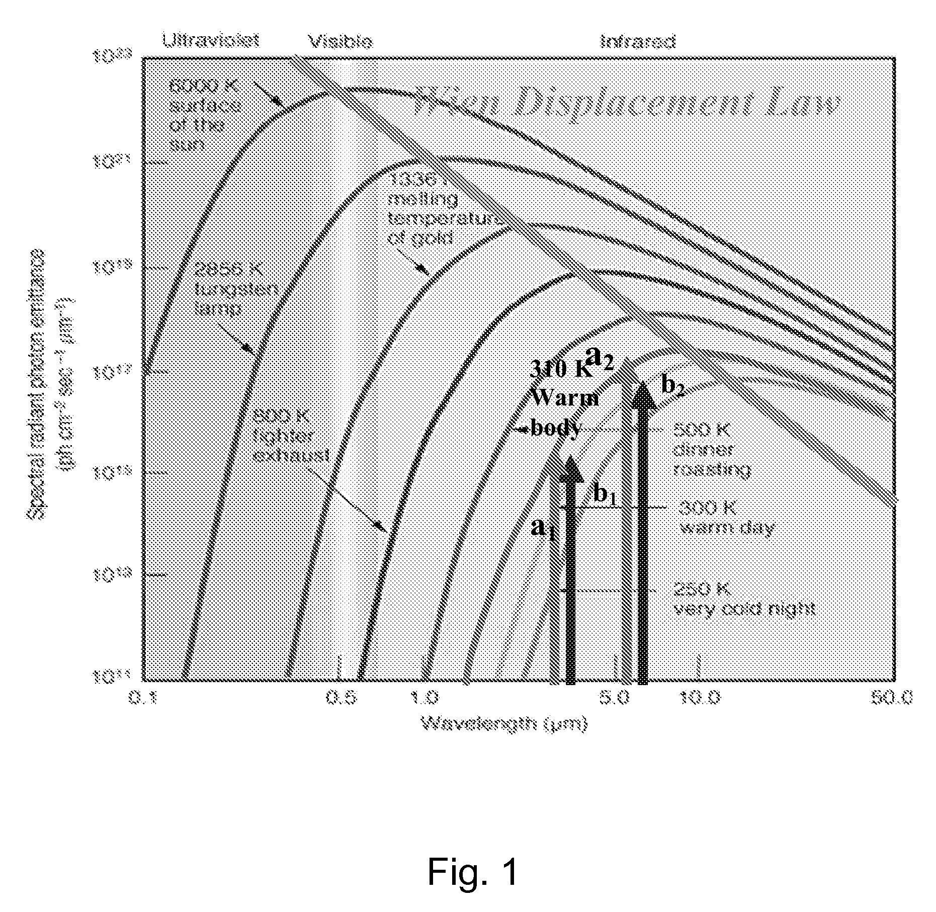
[0041]As shown in FIG. 1, Wien's displacement rule of Planck blackbody cavity radiations is a linear law in terms of the log-log plot of the peak radiation intensity versus the wavelengths, of which Einstein photon dispersion is a special case in a vacuum at the slope m=1. Spectrograms features

abnormal {right arrow over (a)}=(a1,a2); body {right arrow over (b)}=(b1,b2) based on the Planck Radiation Spectrum Distribu...


PUM


Abstract

A process of performing a medical test includes taking multi-spectral images of an area of interest of a patient. The patient can be a human being or an animal, and can be known to be healthy or known to have health issues or problems. A multi-spectral camera includes a long-infrared charge-coupled device, a mid-infrared detector array, and a control device that synchronizes operation of the charge-coupled device and the detector array. The mid-infrared detector array can include carbon nanotubes. The carbon nanotubes can be detector elements. For example, the carbon nanotubes can be tuned-bandgap carbon nanotubes. Each pixel of resolution of the detector array can include a balanced Wheatstone bridge circuit including one of the tuned-bandgap carbon nanotubes. Adjacent pixels of the detector array can be arranged for orthogonal polarization.

Description

CROSS-REFERENCE TO RELATED APPLICATIONS[0001]This is a continuation-in-part of co-pending U.S. patent application Ser. No. 11 / 245,946, which was filed on Oct. 6, 2005, which in turn is related to and claims priority from U.S. Provisional Patent Application Ser. No. 60 / 616,800, which was filed on Oct. 6, 2004.FIELD OF THE INVENTION[0002]The present invention relates to cameras, particularly cameras that provide thermal images for analysis.BACKGROUND OF THE INVENTION[0003]Multi-spectral cameras have long been used for many different applications. Multi-spectral camera systems typically include software for camera control, image acquisition, and image analysis, so that the imaged object can be used for some diagnostic purpose. For example, such images can be used for airborne reconnaissance and terrestrial observation, environmental characterization, and military applications such as target acquisition, camouflage penetration, and surveillance. These cameras are cryogenic, that is, the...

Claims


Application Information

Patent Timeline
IPC IPC(8): G06K9/00H04N5/33
CPCA61B5/0091A61B5/015G01J3/36G06T7/0012G06T7/0022G06T2207/10036G06T2207/10048G06T2207/30068H04N5/33H04N5/332G06T7/97H04N23/11
Inventor SZU, HAROLD
Owner SZU HAROLD
Why Eureka
Try Eureka