
Oil-free centrifugal blade compressor and magnetic-gas bearing thereof

a centrifugal blade compressor and magnetic gas bearing technology, which is applied in the direction of positive displacement liquid engines, piston pumps, liquid fuel engines, etc., can solve the problems of gas bearing instability, low efficiency of compressors with the aforesaid contact-type bearings, and restricted support capacity of gas bearings, so as to achieve low load performance, no contamination, and no friction loss during operation

Active Publication Date: 2012-02-14
IND TECH RES INST
View PDF1 Cites 4 Cited by
  • Summary
  • Abstract
  • Description
  • Claims
  • Application Information

AI Technical Summary

Benefits of technology

The magnetic-gas bearing system achieves high-speed, high-precision operation with reduced shaft power wastage, improved load performance, and enhanced stability, overcoming the limitations of conventional bearings.

Problems solved by technology

However, as such mechanically sealed contact-type bearings can not operate without suffering contact abrasion and they should required to be cooled down by flowing oils during operation, problems such as shaft power wastage and oil vapor pollution are inevitable that are usually the reasons causing those conventional compressors with the aforesaid contact-type bearings to operate at low efficiency.
For the magnetic bearings, they are not popular since they can be very costly to manufacture, not to mention that their ability to support a load are restricted by the magnetic saturation of the bearing's material.
For the gas bearings, the compressibility of the gases used in such gas bearing will cause the gas bearings to become unstable.
However, the load performance of such prior-art magnetic-gas bearing is still not satisfactory and is hard to improve.
In addition, as the magnetic poles in such prior-art magnetic-gas bearing are radially arranged while having its complaint foils to be fitted in the gaps formed between the magnetic poles and its corresponding shaft, the penetration of the magnetic lines of those magnetic poles are adversely affected and thus lower the magnetic levitation of the bearing.

Method used


Image

  • Oil-free centrifugal blade compressor and magnetic-gas bearing thereof
  • Oil-free centrifugal blade compressor and magnetic-gas bearing thereof
  • Oil-free centrifugal blade compressor and magnetic-gas bearing thereof

Examples


Embodiment Construction

[0021]For your esteemed members of reviewing committee to further understand and recognize the fulfilled functions and structural characteristics of the invention, several exemplary embodiments cooperating with detailed description are presented as the follows.

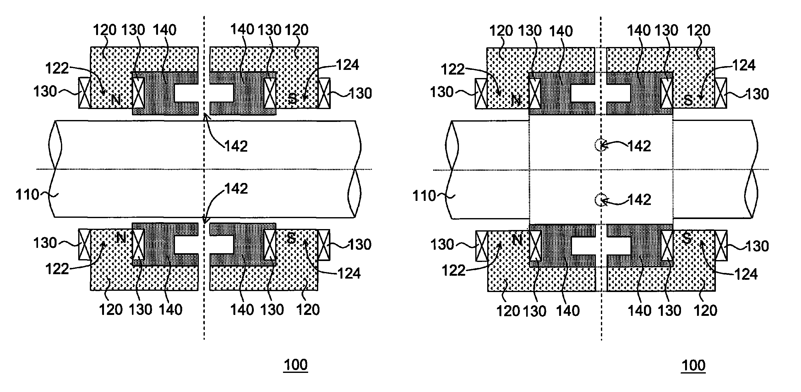
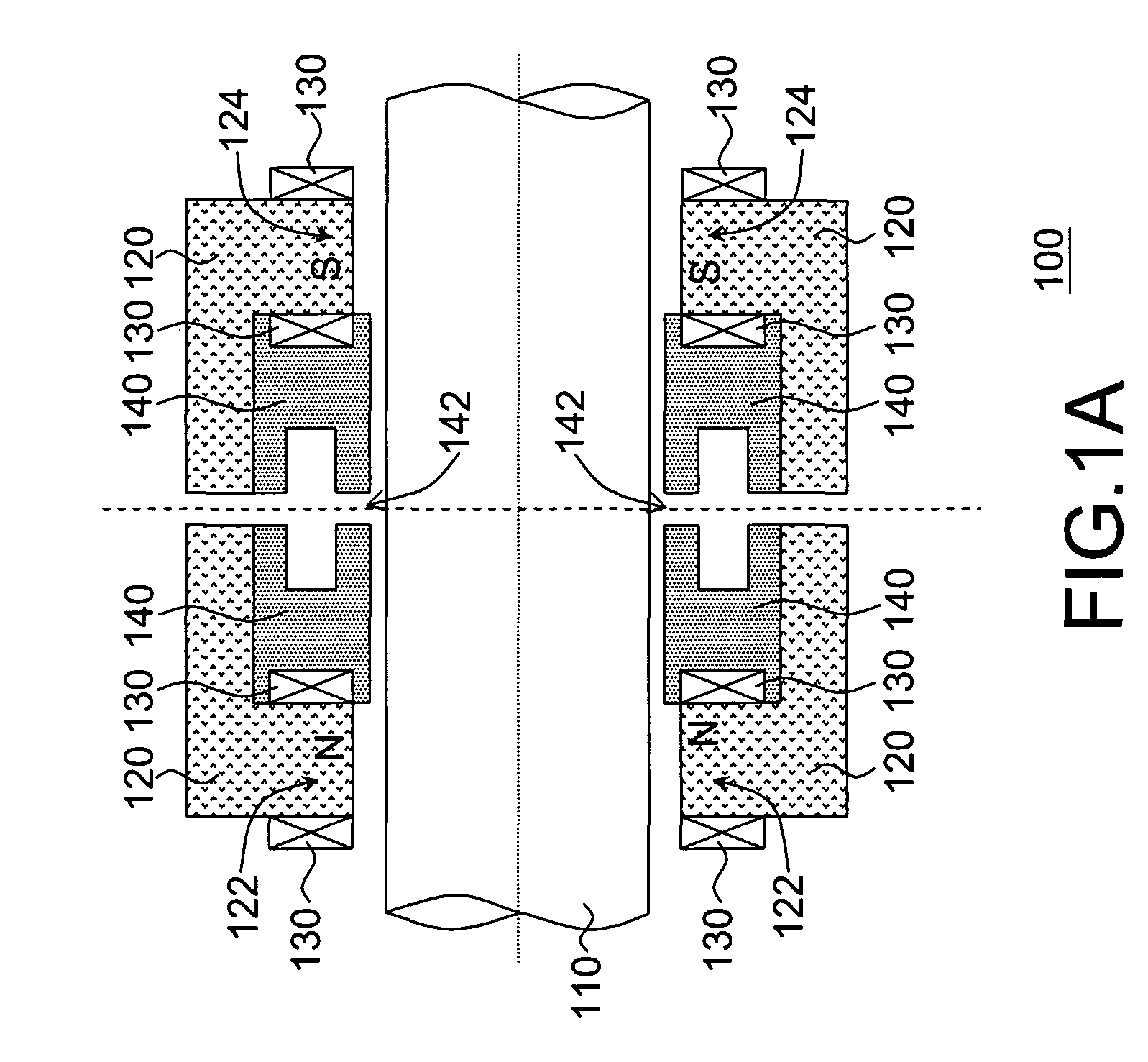
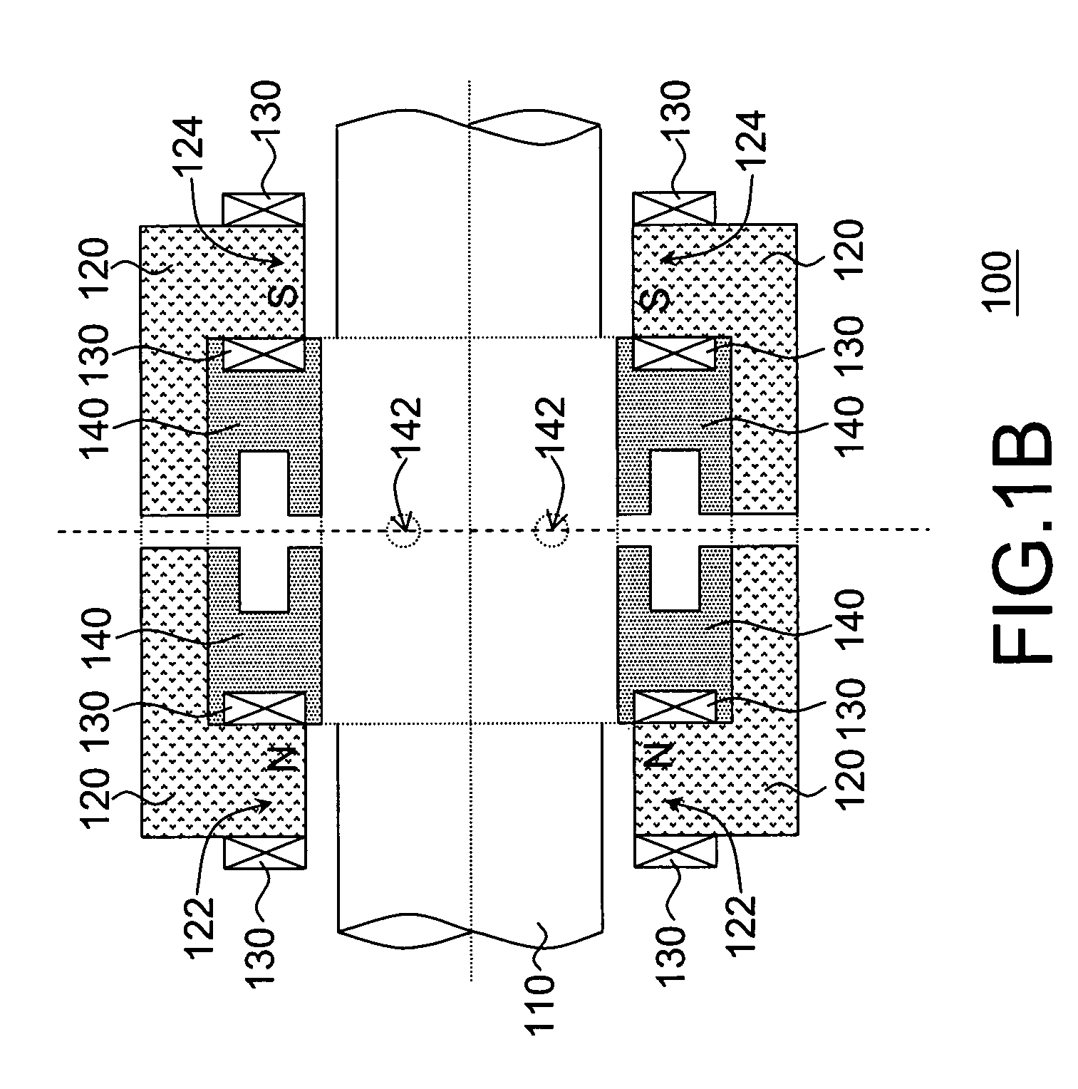
[0022]FIG. 1A is a sectional view of a magnetic-gas bearing according to an embodiment of the invention, and FIG. 1B is a perspective diagram showing a portion of the magnetic-gas bearing of FIG. 1A. As shown in FIG. 1A and FIG. 1B, the magnet-gas bearing 100 is adapted for a compressor, specifically for a centrifugal refrigerant compressor with low shaft power loss. The magnet-gas bearing 100 comprises: an axis 110, a plurality of magnetic elements 120, a plurality of magnetic coils 130 and a static pressure gas restrictor 140, in which the magnetic elements 120 and the magnetic coils 130 are used for controlling the axis 110 in a magnetic manner while the static pressure gas restrictor is used for controlling the axis 110 in...


PUM


Abstract

A magnetic-gas bearing disposed in a compressor is provided. The magnetic-gas bearing includes an axis, multiple magnetic elements, multiple magnetic coils and a static pressure gas restrictor. The magnetic elements encircle the axis, and each magnetic element has two ends wound around by the magnetic coils respectively, such that the two ends of each magnetic element form a first magnetic pole and a second magnetic pole respectively. The static pressure gas restrictor encircles the axis and has a jet opening, such that the gas pass through the jet opening to form a gas-film between the static pressure gas restrictor and the axis. Besides, an oil-free centrifugal blade compressor including the magnetic-gas bearing mentioned above is also provided.

Description

FIELD OF THE INVENTION[0001]The present invention relates to a compressor and its bearing, and more particularly, to an oil-free centrifugal blade compressor and the magnetic-gas bearing thereof.BACKGROUND OF THE INVENTION[0002]Currently, there are three kinds of contact-type bearings that are most commonly being adopted by conventional compressors, which are the ball bearing, the roller bearing and the sliding bearing. However, as such mechanically sealed contact-type bearings can not operate without suffering contact abrasion and they should required to be cooled down by flowing oils during operation, problems such as shaft power wastage and oil vapor pollution are inevitable that are usually the reasons causing those conventional compressors with the aforesaid contact-type bearings to operate at low efficiency.[0003]For avoiding the aforesaid problems, there are magnetic bearings and gas bearings that are already available for the compressors. However, those two types of bearings...

Claims


Application Information

Patent Timeline
Patent Type & Authority Patents(United States)
IPC IPC(8): F04B35/04
CPCF04D29/058H02K7/09
Inventor WU, TENG-YUANYEN, CHENG-CHUNGCHIANG, CHUNG-PINGCHEN, JIING-FU
Owner IND TECH RES INST
Learn More