Power transmission control apparatus for vehicle

a technology for controlling apparatus and transmission, applied in electrical control, mechanical control devices, instruments, etc., can solve problems such as deterioration of the durability of the first clutch, and achieve the effects of reducing the load acting on the first clutch, reducing the operation amount of the acceleration operation member, and increasing the load acting

Inactive Publication Date: 2011-09-29
AISIN AI CO LTD
View PDF14 Cites 22 Cited by
  • Summary
  • Abstract
  • Description
  • Claims
  • Application Information

AI Technical Summary

Benefits of technology

[0023]By virtue of this configuration, the higher the temperature of the first clutch, the grater the value to which the second clutch torque distribution ratio can be set. Thus, the higher the temperature of the first clutch, the lower the level to which the load acting on the first clutch can be reduced. Also, the greater the operation amount of the acceleration operation member, the grater the value to which the second clutch torque distribution ratio can be set. Thus, the greater the load acting on the entire start clutch, the lower the value to which the ratio of the load acting on the first clutch can be reduced. As a result, the occurrence of a situation in which the temperature of the first clutch increases excessively can be prevented more reliably. In addition, the greater the uphill gradient of the road, the smaller the value to which the second clutch torque distribution ratio can be set so as to increase the clutch torque of the first clutch. Thus, the greater the uphill gradient, the greater the drive torque which can be provided to the vehicle. As a result, on an uphill road having a large gradient, the vehicle can be started with a sufficiently large drive force.

Problems solved by technology

As a result, as shown in FIG. 11, the temperature of the first clutch increases excessively, leading to a problem of deteriorated durability of the first clutch.

Method used


Image

  • Power transmission control apparatus for vehicle
  • Power transmission control apparatus for vehicle
  • Power transmission control apparatus for vehicle

Examples


Embodiment Construction

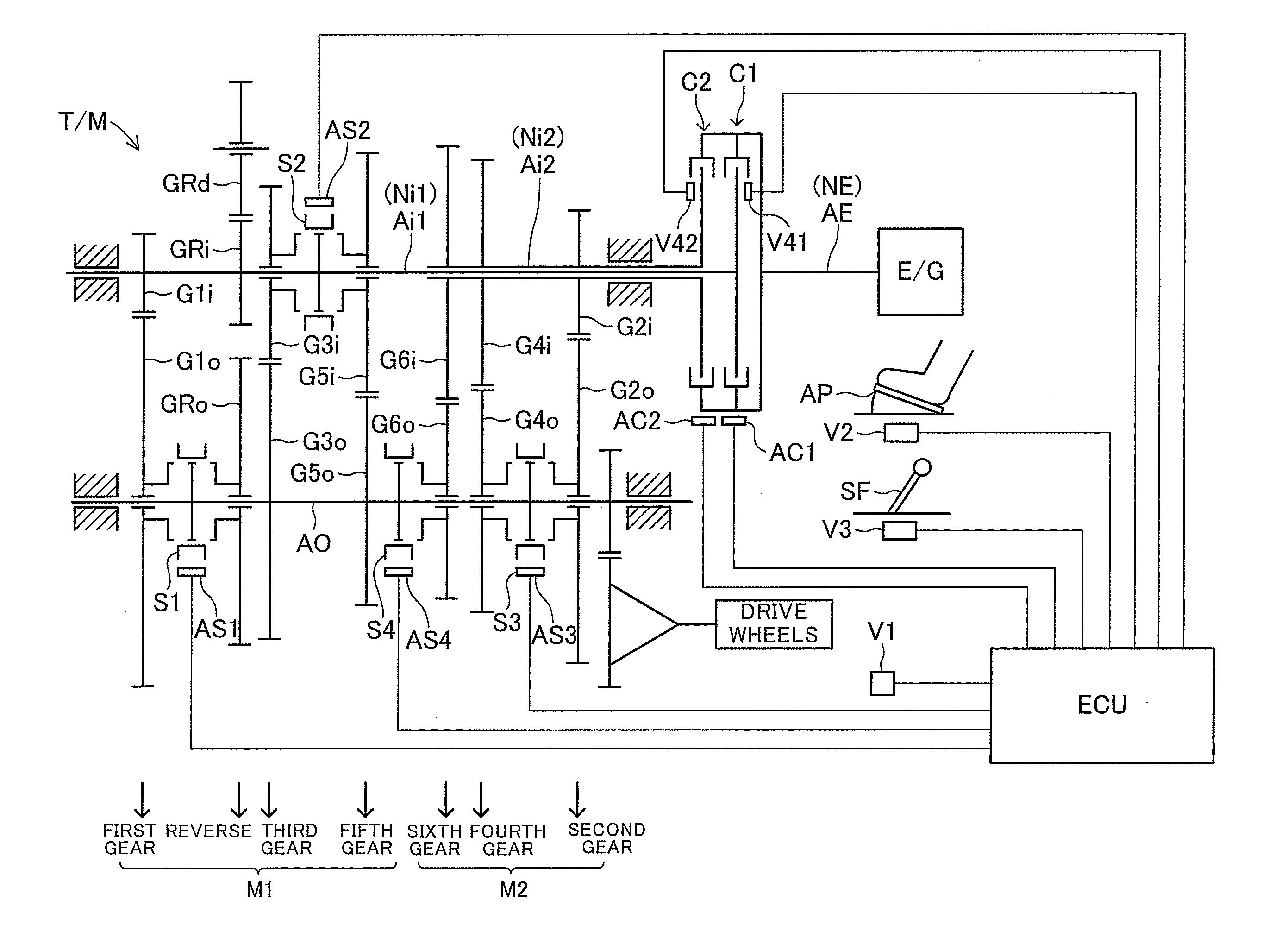
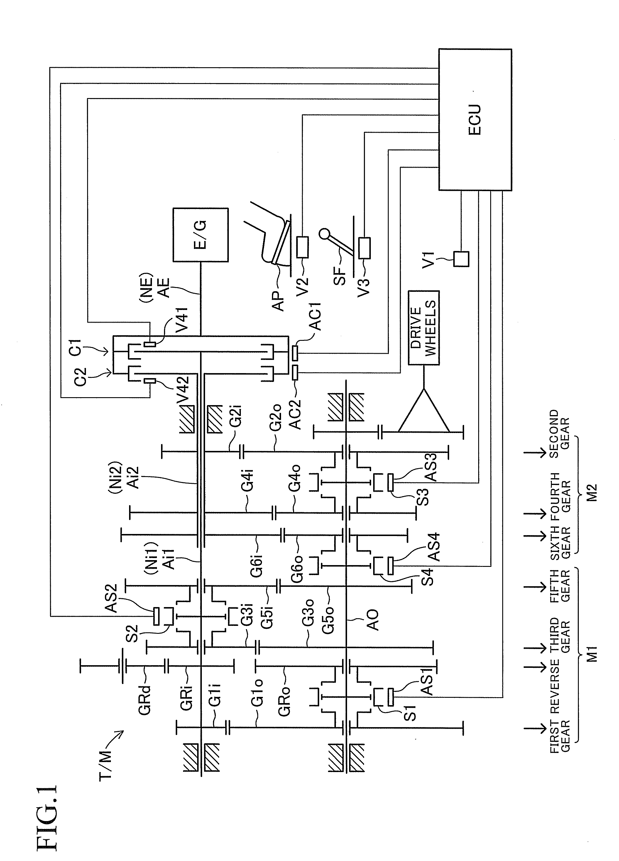
[0039]A power transmission control apparatus for a vehicle according to an embodiment of the present invention (present apparatus) will now be described with reference to the drawings. The present apparatus includes a transmission T / M, a first clutch C1, a second clutch C2, and an ECU. The transmission T / M has six gears (first to sixth gears) for moving the vehicle frontward, and a single gear (reverse gear) for moving the vehicle backward.

[0040]The transmission T / M includes a first input shaft Ai1, a second input shaft Ai2, an output shaft AO, a first mechanism section M1, and a second mechanism section M2. The first and second input shafts Ai1, Ai2 are coaxially supported by a casing (not shown) such that they can rotate relative to each other. The output shaft AO is supported by the casing at a position shifted from the first and second input shafts Ai1, Ai2, and in parallel with the first and second input shafts Ai1, Ai2.

[0041]The first input shaft Ai1 is connected via the first...


PUM


Abstract

First and second clutches correspond to systems which include “first gear” and “second gear,” respectively. When the temperature of the first clutch at the time of start of the vehicle is lower than a first temperature, only the first clutch is used as a start clutch for driving the vehicle. When the temperature of the first clutch is not lower than the first temperature but is lower than a second temperature, both the first and second clutches are used as the start clutch. When the temperature of the first clutch is equal to or higher than the second temperature, only the second clutch is used as the start clutch. Thus, the higher the temperature of the first clutch, the smaller the load acting on the first clutch. When the temperature of the second clutch is high, engine torque is reduced, and a warning is issued.

Description

BACKGROUND OF THE INVENTION[0001]1. Field of the Invention[0002]The present invention relates to a power transmission control apparatus for a vehicle.[0003]2. Description of the Related Art[0004]As described in, for example, Japanese Patent Application Laid-Open (kokai) No. 2010-48416, there has been known a transmission which includes first and second input shafts for receiving power from an engine of a vehicle; an output shaft for outputting power to drive wheels of the vehicle; a first mechanism section which selectively establishes any one of some (odd gears including first gear) of all the gears to thereby form a power transmission system between the first input shaft and the output shaft; and a second mechanism section which selectively establishes any one of the remaining gears (even gears including second gear) to thereby form a power transmission system between the second input shaft and the output shaft.[0005]This transmission includes first and second clutches in combinat...

Claims


Application Information

Patent Timeline
Patent Type & Authority Applications(United States)
IPC IPC(8): F16H59/14F16H59/00F16H59/68
CPCF16H2059/725F16D2500/1086F16H61/688Y10T74/20018F16D2500/30404F16D2500/506F16D48/08F16D2500/5102F16D2500/5106F02D41/022F16D2500/50224
Inventor TSUJIMURA, MANABUMIYAZAKI, TAKESHIGE
Owner AISIN AI CO LTD
Why Eureka
Try Eureka