System and method for reducing loads acting on a wind turbine in response to transient wind conditions

a technology of wind turbines and load reduction, applied in the field of wind turbines, can solve the problems of increasing the risk of a tower strike, rapid blade loading, and the implementation of control strategies, and achieve the effect of reducing the load acting on the wind turbin

Active Publication Date: 2014-09-18
GENERAL ELECTRIC CO
View PDF6 Cites 25 Cited by
  • Summary
  • Abstract
  • Description
  • Claims
  • Application Information

AI Technical Summary

Benefits of technology

[0007]In one aspect, the present subject matter is directed to a method for reducing loads acting on a wind turbine in response to transient wind conditions. The method may generally include determining an actual value for a blade parameter of a rotor blade of the wind turbine using a first sensor associated with the rotor blade, monitoring a secondary operating parameter of the wind turbine using a second sensor, determining a predicted value for the blade parameter based on the secondary operating parameter, comparing the actual value to the predicted value and performing a corrective action to reduce the loads acting on the wind turbine if the actual value differs from the predicted value by at least a differential threshold.

Problems solved by technology

Transient wind conditions often present challenges for implementing control strategies to maintain the loads acting on wind turbine rotor blades and other wind turbine components at relatively low levels.
For example, during extreme wind gusts, the wind speed may increase significantly in a relatively short period of time, leading to a rapid increase in blade loading.
This rapid increase initially impacts the outboard portions of the rotor blades (e.g., at the tip) where the blades are more susceptible to increased deflection due to loading, which can result in an increased risk of a tower strike due to excessive tip deflection.
However, due to rotor inertia, changes in generator speed lag behind changes in blade loading.
As a result, current control strategies may not be sufficiently responsive in reducing blade loading during extreme transient events.

Method used


Image

  • System and method for reducing loads acting on a wind turbine in response to transient wind conditions
  • System and method for reducing loads acting on a wind turbine in response to transient wind conditions
  • System and method for reducing loads acting on a wind turbine in response to transient wind conditions

Examples


Embodiment Construction

[0018]Reference now will be made in detail to embodiments of the invention, one or more examples of which are illustrated in the drawings. Each example is provided by way of explanation of the invention, not limitation of the invention. In fact, it will be apparent to those skilled in the art that various modifications and variations can be made in the present invention without departing from the scope or spirit of the invention. For instance, features illustrated or described as part of one embodiment can be used with another embodiment to yield a still further embodiment. Thus, it is intended that the present invention covers such modifications and variations as come within the scope of the appended claims and their equivalents.

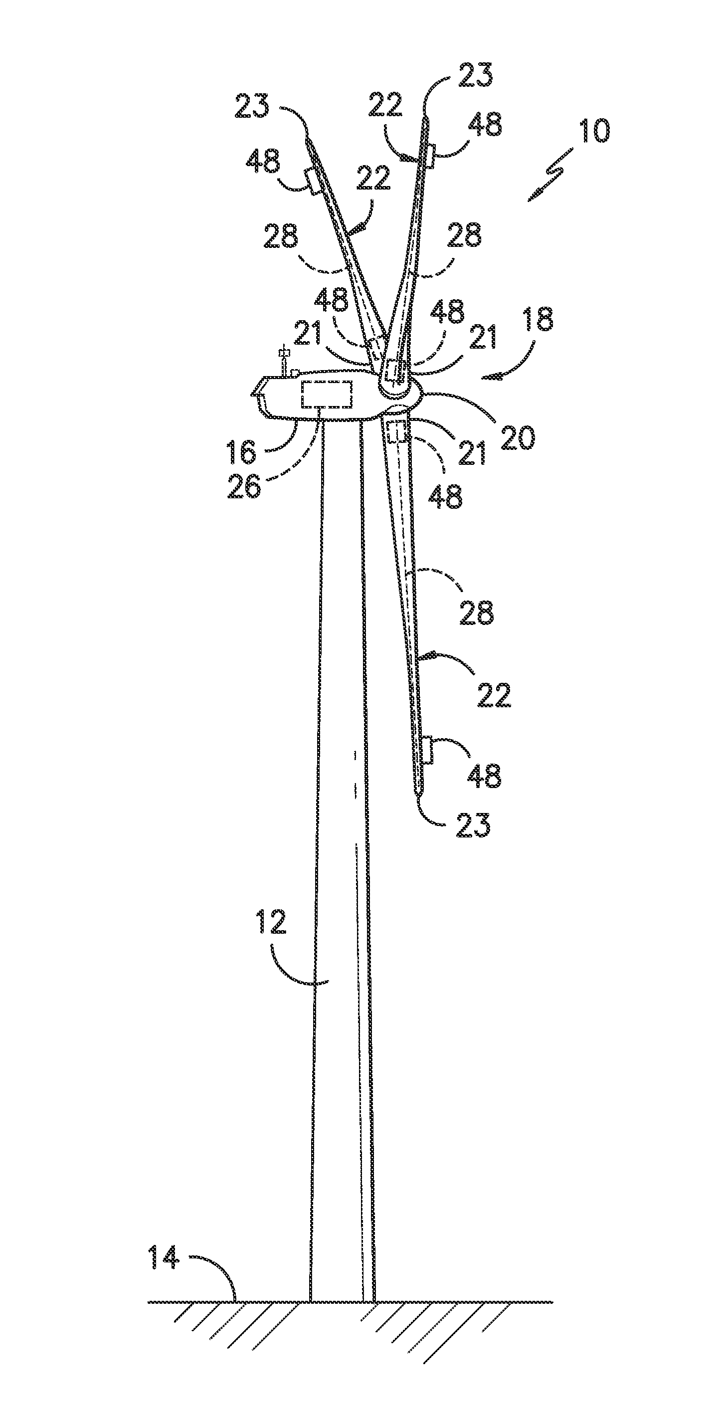
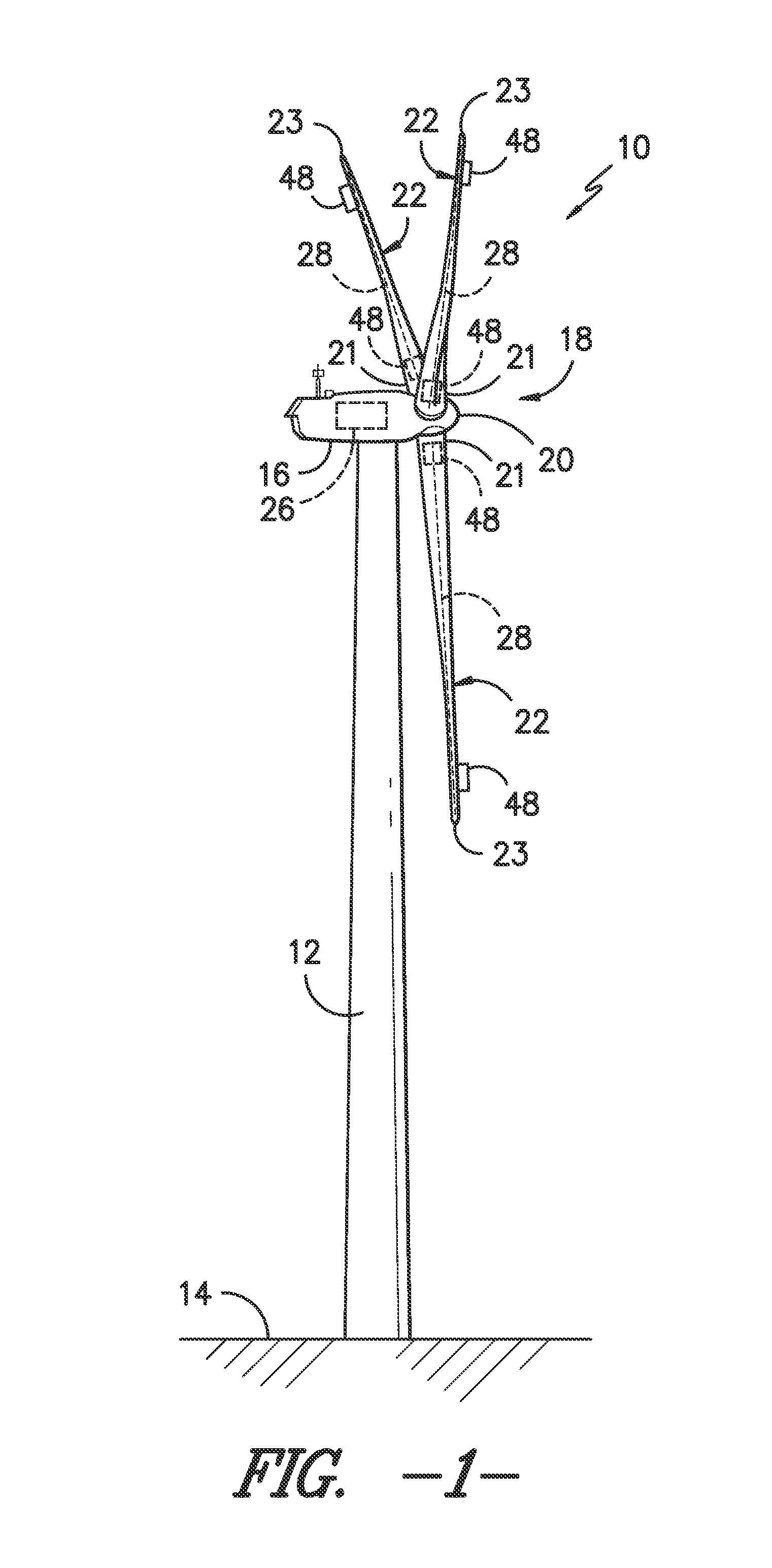
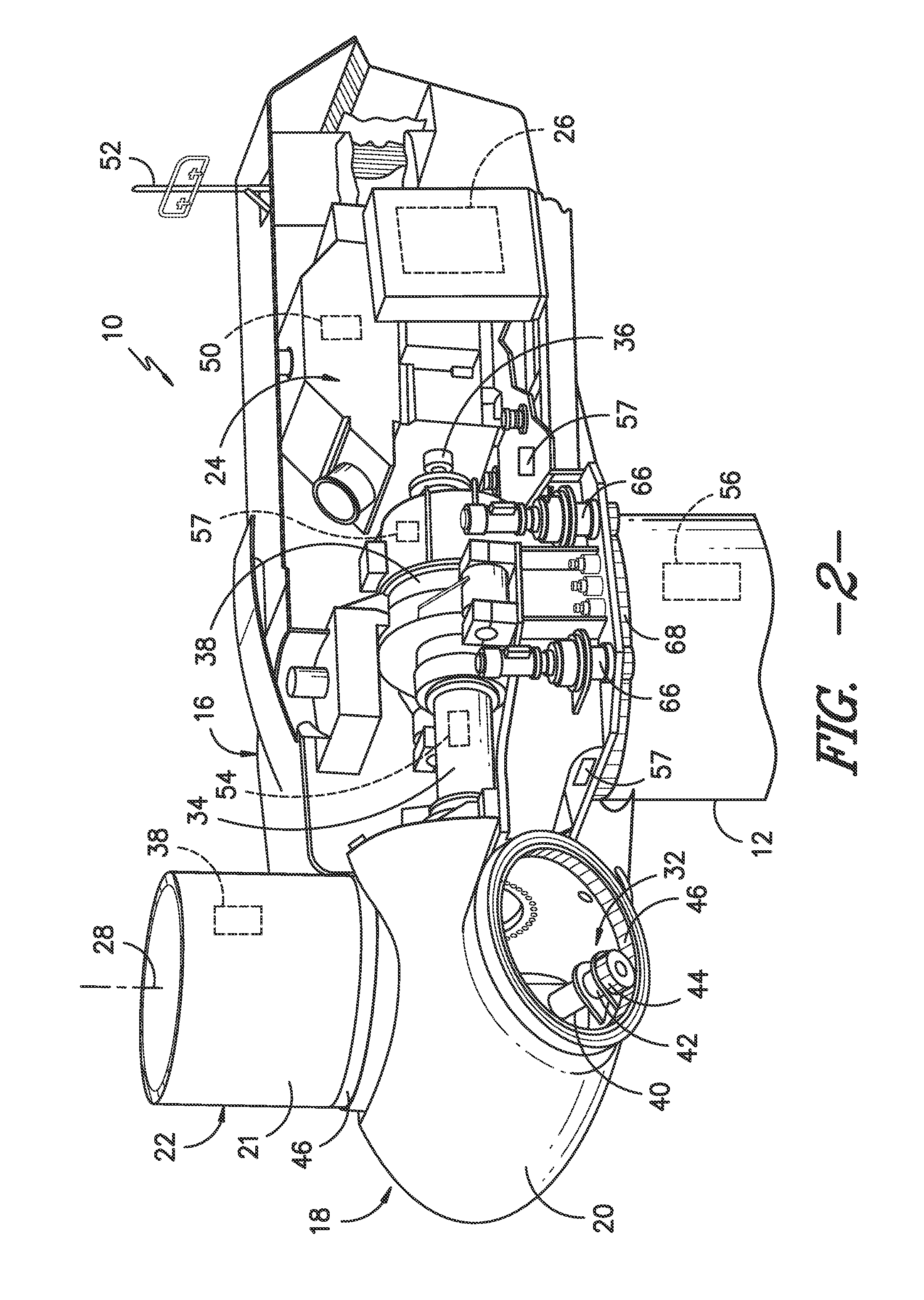
[0019]In general, the present subject matter is directed to a system and method for reducing the loads acting on rotor blades and / or other wind turbine components in response to transient wind conditions. Specifically, one or more blade sensors may be used ...


PUM


Abstract

A method for reducing loads acting on a wind turbine in response to transient wind conditions is disclosed. The method may generally include determining an actual value for a blade parameter of a rotor blade of the wind turbine using a first sensor associated with the rotor blade, monitoring a secondary operating parameter of the wind turbine using a second sensor, determining a predicted value for the blade parameter based on the secondary operating parameter, comparing the actual value to the predicted value and performing a corrective action to reduce the loads acting on the wind turbine if the actual value differs from the predicted value by at least a differential threshold.

Description

FIELD OF THE INVENTION[0001]The present subject matter relates generally to wind turbines and, more particularly, to systems and methods for reducing the loads on wind turbine components in response to transient wind conditions.BACKGROUND OF THE INVENTION[0002]Generally, a wind turbine includes a tower, a nacelle mounted on the tower, and a rotor coupled to the nacelle. The rotor typically includes a rotatable hub and a plurality of rotor blades coupled to and extending outwardly from the hub. Each rotor blade may be spaced about the hub so as to facilitate rotating the rotor to enable kinetic energy to be transferred from the wind into usable mechanical energy, and subsequently, electrical energy.[0003]Transient wind conditions often present challenges for implementing control strategies to maintain the loads acting on wind turbine rotor blades and other wind turbine components at relatively low levels. For example, during extreme wind gusts, the wind speed may increase significant...

Claims


Application Information

Patent Timeline
Patent Type & Authority Applications(United States)
IPC IPC(8): F03D7/04
CPCF03D7/04F03D7/0224F03D7/045F05B2260/845F05B2270/328F05B2270/331F03D17/00F05B2260/84F05B2260/821Y02E10/72F03D7/042F03D7/024F05B2270/335F03D7/00F05B2260/70F05B2260/80
Inventor PERLEY, THOMAS FRANKLINGERBER, BRANDON SHANERASTOGI, RAHUL
Owner GENERAL ELECTRIC CO
Why Eureka
Try Eureka