Aggregate load management at a system level

a load management and system level technology, applied in the field of energy management, can solve problems such as major disruption to consumers, affecting their quality of life, harming equipment in homes,

Active Publication Date: 2013-08-22
HAIER US APPLIANCE SOLUTIONS INC
View PDF11 Cites 27 Cited by
  • Summary
  • Abstract
  • Description
  • Claims
  • Application Information

AI Technical Summary

Benefits of technology

[0004]As described herein, the exemplary embodiments of the present invention overcome one or more disadvantages known in the art.
[0005]One aspect of the present invention relates to a method for aggregate load management. The method includes determining whether a load capacity limit within a utility power network will be exceeded, selecting an aggregated demand reduction target to remain within capacity bounds if the load capacity limit is to be exceeded, selecting a demand reduction strategy, and sending a control signal that includes a randomized pulse width modulation level, based on the strategy selected, to a controller in at least one load component of the utility system based on the reduction target.
[0006]Another aspect relates to a system for aggregate load management. The system includes at least one distinct software module, each distinct software module being embodied on a tangible computer-readable medium, a memory, and at least one processor coupled to the memory and operative for determining whether a load capacity limit within a utility power network will be exceeded, selecting an aggregated demand reduction target to remain within capacity bounds if the load capacity limit is to be exceeded, selecting a demand reduction strategy, and sending a control signal that includes a randomized pulse width modulation level, based on the strategy selected, to a controller in at least one load component of the utility system based on the reduction target.
[0007]Yet another aspect of the present invention relates to a method for load management at a component level. The method includes receiving, via a controller in a load component, a control signal from a utility system based on a utility demand reduction strategy, converting the control signal into a randomized pulse width modulation control of the load component in accordance with the control signal, receiving, via the controller in the load component, an updated control signal from the utility system based on utility system monitoring of an aggregate load of at least one component of the utility system, and converting the updated control signal into a randomized pulse width modulation control of the load component in accordance with the updated control signal.

Problems solved by technology

Also, similar methods are used on a local level if the capacity of distribution system components cannot support the local demand.
Such methods result in major disruption to consumers, significantly impacting their quality of life and in some cases harming equipment in homes.
In addition, such methods are applied at a bulk level and cannot be adjusted to reduce power by a determined controlled amount.

Method used


Image

  • Aggregate load management at a system level
  • Aggregate load management at a system level
  • Aggregate load management at a system level

Examples


Embodiment Construction

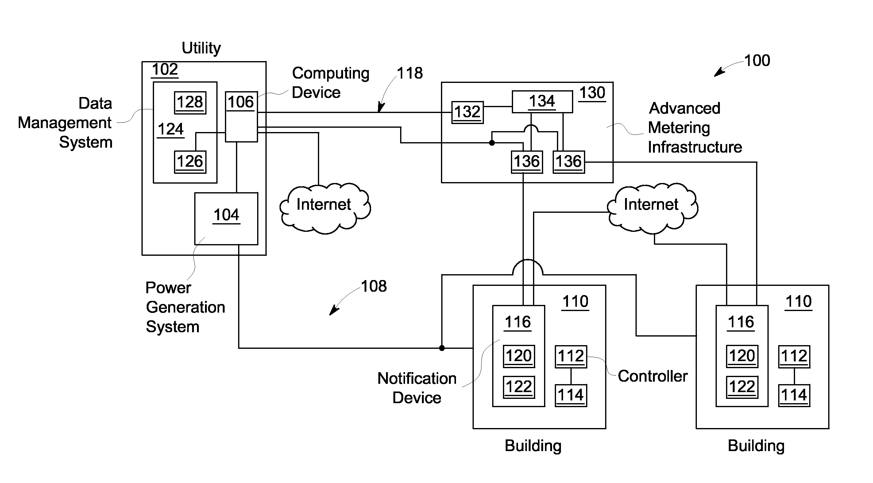
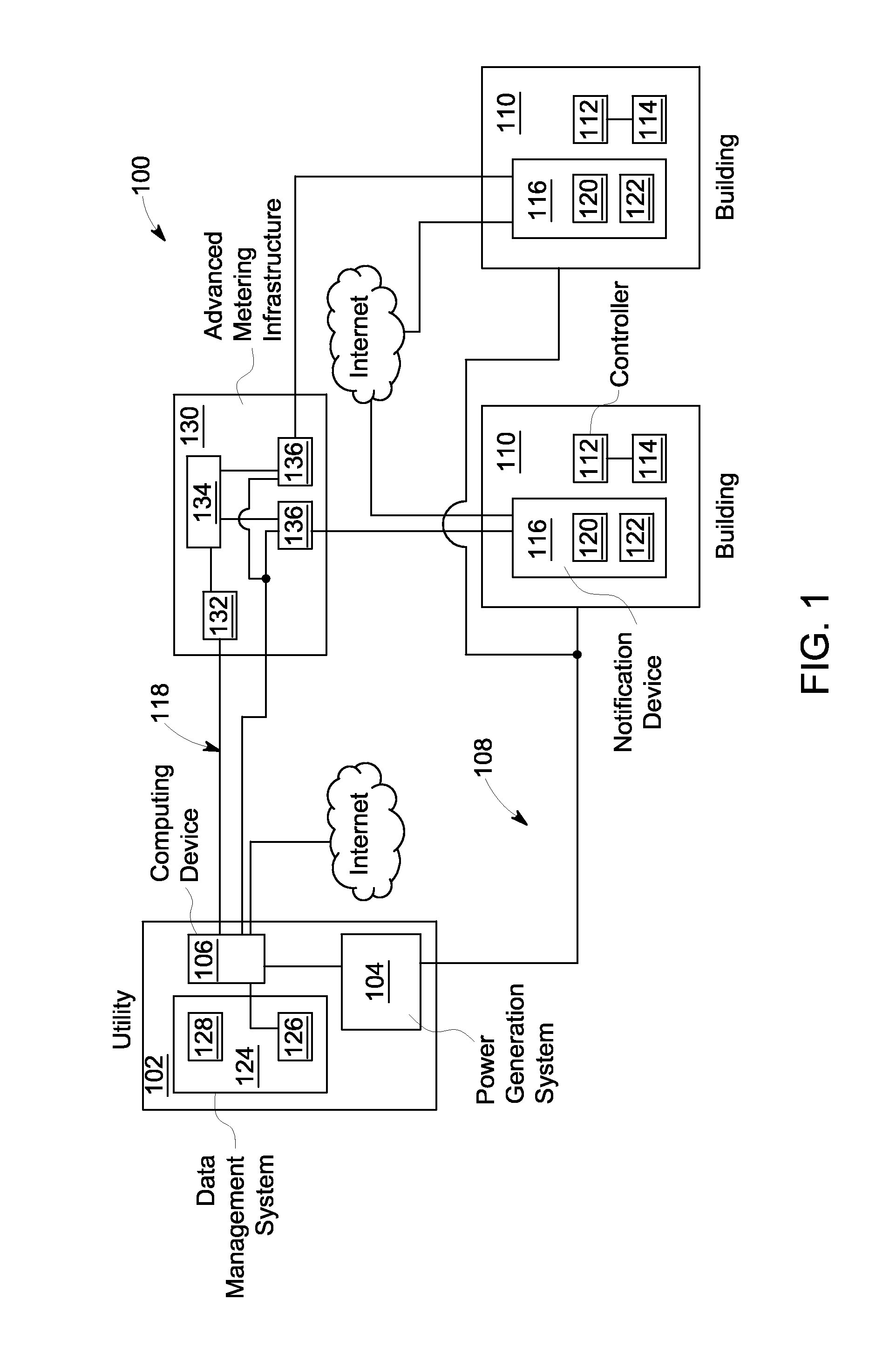
[0015]As described herein, one or more embodiments of the invention include application of a low frequency pulse width modulation (PWM) method for aggregate load management at a neighborhood or system level. As detailed herein, power consuming devices that are generally either off or on for a period of time (e.g., a heating, ventilation, and air conditioning compressor, a water heater, an irrigation pump, a pool pump, etc.) can be controlled using low frequency PWM control (also referred to herein as duty cycle control). Time is divided into control periods having a generally fixed period on the order of minutes and a controller determines how long a power consuming device is to be operated (i.e., turned-on) during each control period to achieve a desired result, such as a desired temperature. The percentage of a control period during which a power consuming device is turned on is referred to as the duty cycle at which the device is operated. Embodiments described herein enable limi...


PUM


Abstract

A method for aggregate load management includes determining whether a load capacity limit within a utility power network will be exceeded, selecting an aggregated demand reduction target to remain within capacity bounds if the load capacity limit is to be exceeded, selecting a demand reduction strategy, and sending a control signal that includes a randomized PWM level, based on the strategy, to a controller in a load component of the utility system based on the reduction target. A method for component load management includes receiving a control signal from a utility system based on a utility demand reduction strategy, converting the signal into randomized PWM control of the load component in accordance therewith, receiving an updated control signal based on utility system monitoring of an aggregate load of a component of the utility system, and converting the updated signal into randomized PWM control of the load component in accordance therewith.

Description

CROSS-REFERENCE TO RELATED APPLICATIONS[0001]The present application is related to U.S. patent application entitled “Synchronized PWM Randomization for Coordinated Load Management,” identified by attorney docket number 248024, and filed concurrently herewith, the disclosure of which is incorporated by reference herein in its entirety.BACKGROUND OF THE INVENTION[0002]The subject matter disclosed herein relates generally to energy management, and more particularly to energy management at a neighborhood or system level.[0003]Electric utilities use methods such as voltage reductions, rolling blackouts or direct load control (cycling of heating, ventilation, and air conditioning (HVAC) systems) to prevent outages during periods when energy generation cannot meet the system demand. Also, similar methods are used on a local level if the capacity of distribution system components cannot support the local demand. Such methods result in major disruption to consumers, significantly impacting t...

Claims


Application Information

Patent Timeline
Patent Type & Authority Applications(United States)
IPC IPC(8): G05F5/00
CPCY02B70/3241Y04S20/227G05B15/02H02J13/0079Y02B70/3225Y04S20/222H02J3/14G05B2219/2642Y04S50/16G06Q50/06H02J3/144H02J13/00017H02J13/00028H02J13/00034Y04S40/124Y02E60/00G16Z99/00Y02B70/30Y04S20/20
Inventor NAJEWICZ, DAVID JOSEPHSMITH, CHARLES RAYDRAKE, JEFF DONALDBURKE, WILILAM JEROME
Owner HAIER US APPLIANCE SOLUTIONS INC
Why Eureka
Try Eureka