Method and system for automatically rerouting logical circuit data from a logical circuit failure to dedicated backup circuit in a data network

a technology of logical circuit and backup physical circuit, which is applied in the direction of data switching network, frequency-division multiplex, instruments, etc., can solve the problems of increasing the time it will take to reroute the logical circuit data, the current backup services provided by network circuit providers do not offer backup logical circuits provisioned over the backup physical circuit, and the loss of data, so as to minimize the loss of data

Active Publication Date: 2008-12-16
AT&T INTPROP I LP
View PDF7 Cites 43 Cited by
  • Summary
  • Abstract
  • Description
  • Claims
  • Application Information

AI Technical Summary

Benefits of technology

[0008]In accordance with the present invention, the above and other problems are solved by a method and system for automatically rerouting logical circuit data from a logical circuit failure to a dedicated backup circuit in a data network. When a failure in a logical circuit is detected, a label or services name associated with the logical circuit is automatically associated with a logical circuit identifier utilized for identifying the logical circuit in the data network. Once the logical circuit is associated with the logical circuit identifier, the logical circuit data may be automatically rerouted to a “failover network,” thereby minimizing lost data until the failure in the logical circuit is resolved.

Problems solved by technology

Periodically, failures may occur to the trunk circuits or the NNIs of network circuits in large-scale networks causing lost data.
However, current backup services provided by network circuit providers do not offer backup logical circuits provisioned over the backup physical circuit prior to a network circuit failure.
This provisioning process increases the time it will take to reroute the logical circuit data over the backup logical circuits.

Method used


Image

  • Method and system for automatically rerouting logical circuit data from a logical circuit failure to dedicated backup circuit in a data network
  • Method and system for automatically rerouting logical circuit data from a logical circuit failure to dedicated backup circuit in a data network
  • Method and system for automatically rerouting logical circuit data from a logical circuit failure to dedicated backup circuit in a data network

Examples


Embodiment Construction

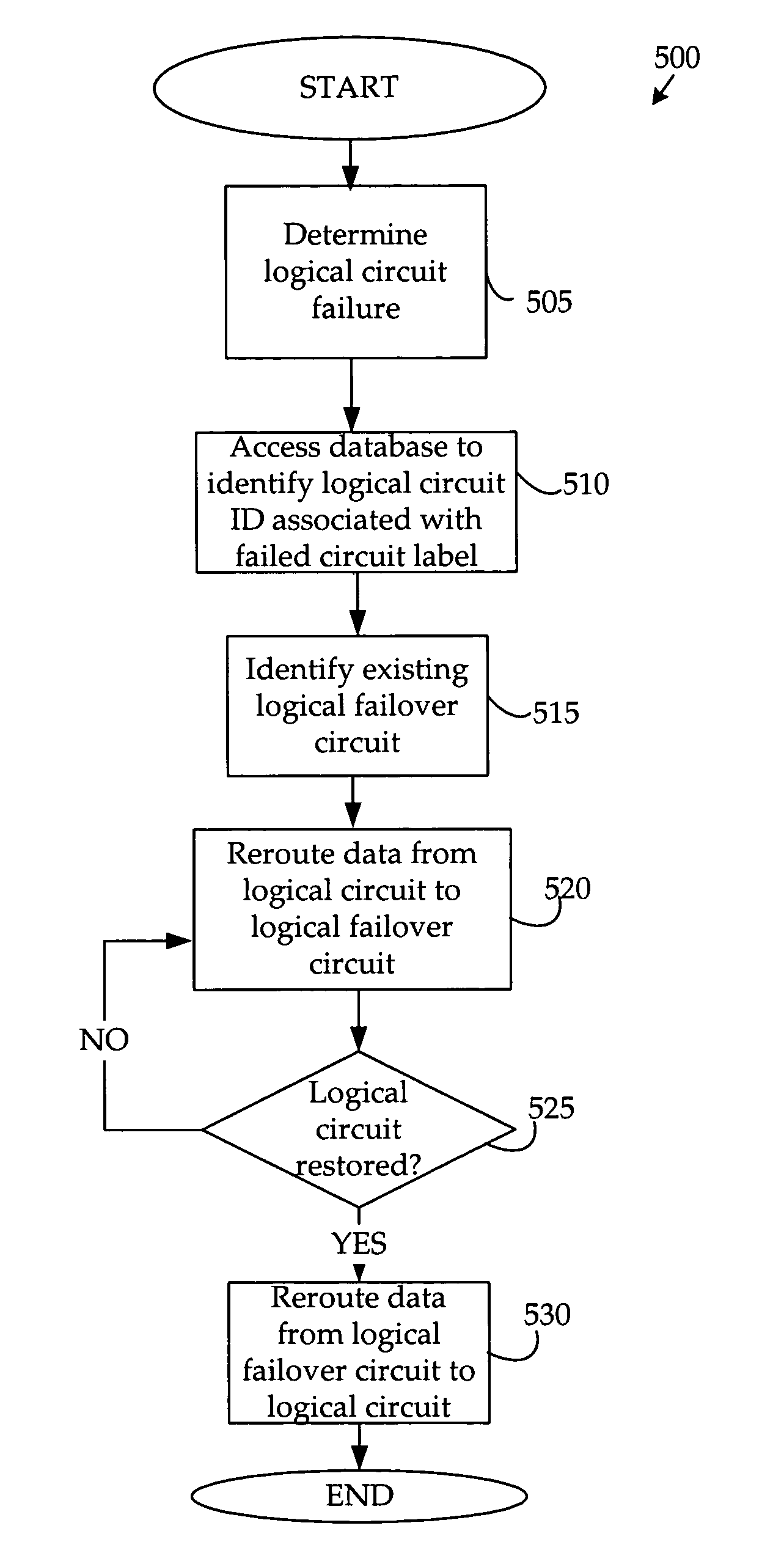
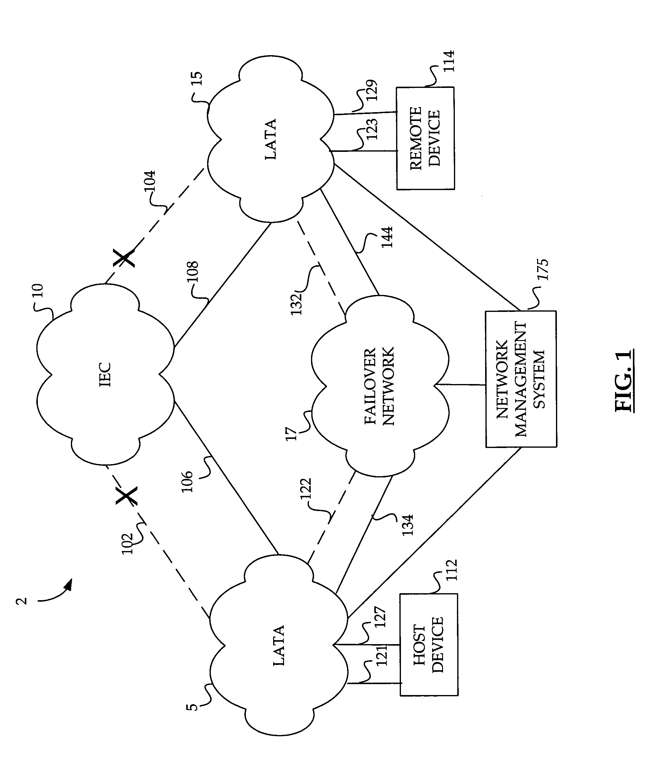
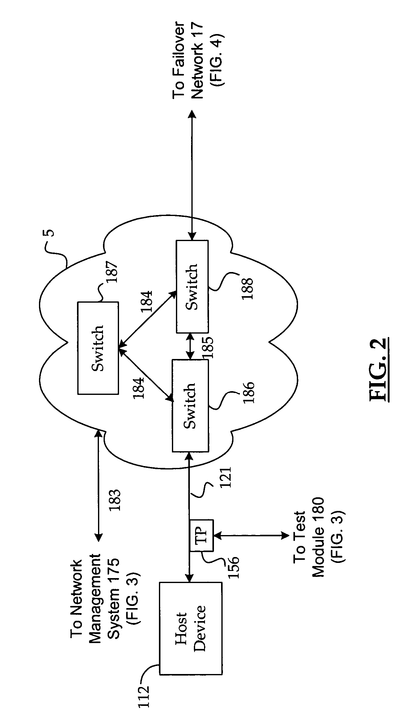
[0018]Embodiments of the present invention provide for a method and system for automatically rerouting logical circuit data from a logical circuit failure to a dedicated backup circuit in a data network. When a failure in a logical circuit is detected, a label or services name associated with the logical circuit is automatically associated with a logical circuit identifier utilized for identifying the logical circuit in the data network. Once the logical circuit is associated with the logical circuit identifier, the logical circuit data may be automatically rerouted to a “failover network,” thereby minimizing lost data until the failure in the logical circuit is resolved. In the following detailed description, references are made to the accompanying drawings that form a part hereof, and in which are shown by way of illustration specific embodiments or examples. Referring now to the drawings, in which like numerals represent like elements through the several figures, aspects of the p...


PUM


Abstract

A method and system are provided for automatically rerouting logical circuit data from a physical circuit failure in a data network. When a failure in a logical circuit is detected, a label or services name associated with the logical circuit is automatically associated with a logical circuit identifier utilized for identifying the logical circuit in the data network. Once the logical circuit is associated with the logical circuit identifier, the logical circuit data may be automatically rerouted to a “failover network,” thereby minimizing lost data until the failure in the logical circuit is resolved. The logical failover circuit may be an already existing logical circuit provisioned over a dedicated backup physical circuit in the data network.

Description

CROSS-REFERENCE TO RELATED APPLICATIONS[0001]The present application is related to U.S. patent application Ser. No. 10 / 348,077, entitled “Method and System for Obtaining Logical Performance Data for a Circuit in a Data Network,” filed on Jan. 21, 2003, and U.S. patent application Ser. No. 10 / 348,592, entitled “Method and System for Provisioning and Maintaining a Circuit in a Data Network,” filed on Jan. 21, 2003. This application is also related to and filed concurrently with U.S. patent application Ser. No. 10 / 745,117, entitled “Method And System For Providing A Failover Circuit For Rerouting Logical Circuit Data In A Data Network,” U.S. patent application Ser. No. 10 / 745,170, entitled “Method And System For Automatically Identifying A Logical Circuit Failure In A Data Network,” filed on Dec. 23, 2003, and “Method And System For Automatically Rerouting Logical Circuit Data In A Data Network,” filed on Dec. 23, 2003. All of the above-referenced applications are assigned to the same ...

Claims


Application Information

Patent Timeline
Patent Type & Authority Patents(United States)
IPC IPC(8): G01R31/08G06F11/00G08C15/00H04L12/26H04L12/56
CPCH04L45/10H04L45/22H04L45/28H04L41/0654G06F11/2002
Inventor TAYLOR, WILLIAMMASSENGILL, DAVIDHOLLINGSWORTH, JOHN
Owner AT&T INTPROP I LP
Why Eureka
Try Eureka