Method and system for automatically rerouting logical circuit data in a data network

a data network and logical circuit technology, applied in data switching networks, instruments, frequency-division multiplexes, etc., can solve problems such as time-consuming troubleshooting of logical and physical circuits, loss of data, and current methods of determining network circuit failures, so as to minimize data loss

Active Publication Date: 2012-06-12
RAKUTEN GRP INC
View PDF179 Cites 34 Cited by
  • Summary
  • Abstract
  • Description
  • Claims
  • Application Information

AI Technical Summary

Benefits of technology

[0008]In accordance with the present invention, the above and other problems are solved by methods for automatically utilizing logical failover circuits for rerouting data from failed logical circuits in a data network. When a failure in a logical circuit is detected, the data in the circuit may be rerouted to a “logical failover network,” thereby minimizing lost data until the trouble in the logical circuit is resolved.

Problems solved by technology

Periodically, failures may occur to the trunk circuits or the NNIs of network circuits in large-scale networks causing lost data.
Current methods of determining network circuit failures, however, suffer from several drawbacks.
One drawback is that troubleshooting logical and physical circuits is time consuming and results in dropped data packets or cells until the failure is isolated and repaired.
Furthermore troubleshooting the physical circuit often requires taking the network circuit out of service to perform testing, thus increasing the downtime and loss of data in the logical circuit.
Moreover, if the failure cannot be isolated by the technicians in a LATA or the failure is located at the interface to the IEC, cooperative testing with the IEC must also be coordinated to isolate the failure leading to a further increase in downtime and loss of data in the network circuit.

Method used


Image

  • Method and system for automatically rerouting logical circuit data in a data network
  • Method and system for automatically rerouting logical circuit data in a data network
  • Method and system for automatically rerouting logical circuit data in a data network

Examples


Embodiment Construction

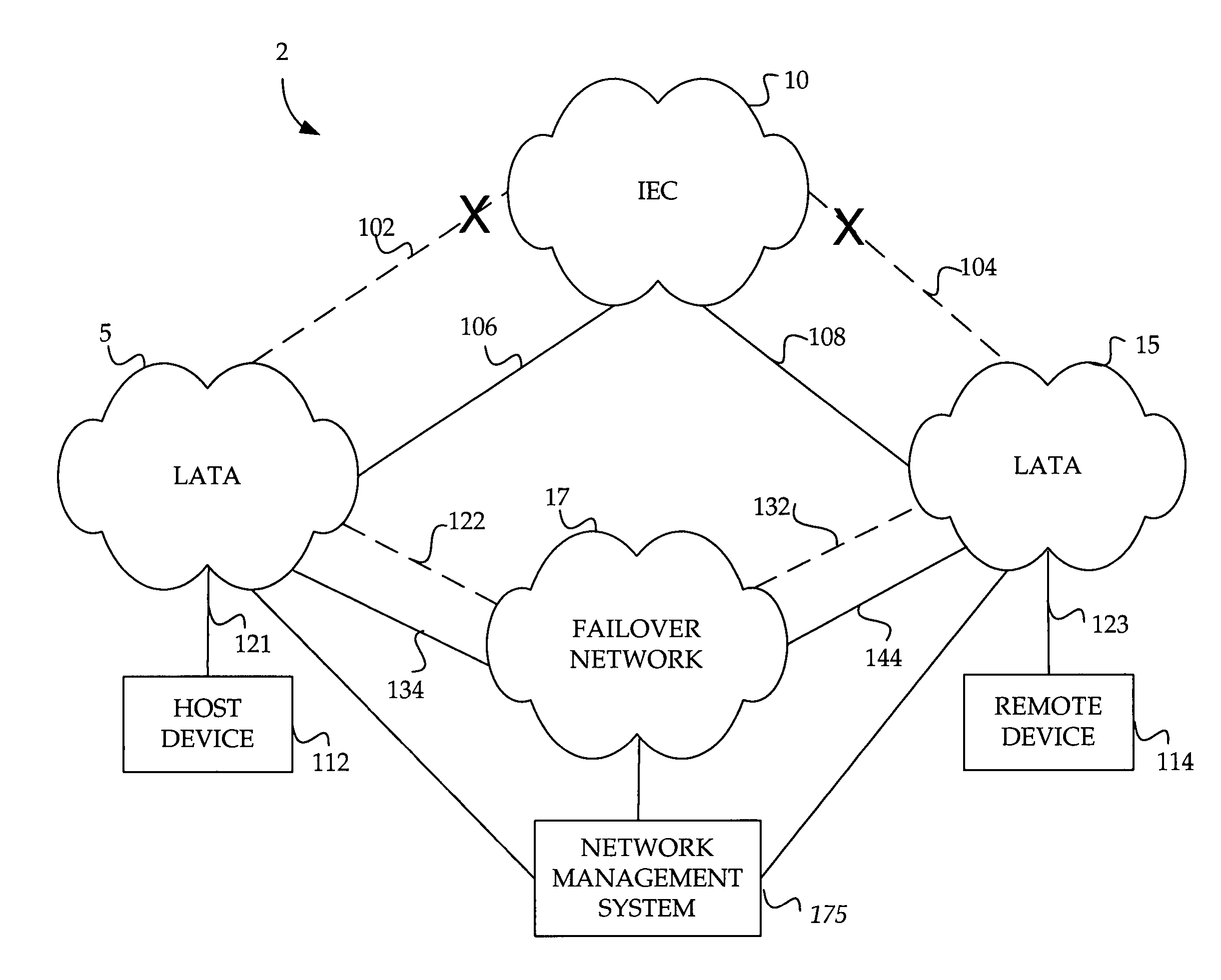
[0019]Embodiments of the present invention provide for a method and system for utilizing a logical failover circuit for automatically rerouting data from a logical circuit in a data network. When a failure in a logical circuit is detected, the data in the circuit may be rerouted to a “failover network,” thereby minimizing lost data until the failure in the logical circuit is resolved. In the following detailed description, references are made to the accompanying drawings that form a part hereof, and in which are shown by way of illustration specific embodiments or examples. Referring now to the drawings, in which like numerals represent like elements through the several figures, aspects of the present invention and the exemplary operating environment will be described.

[0020]Embodiments of the present invention may be generally employed in a data network 2 as shown in FIG. 1. The data network 2 includes local access and transport areas (“LATAs”) 5 and 15 which are connected by an Int...


PUM


Abstract

A method and system are provided for automatically rerouting logical circuit data in a data network. A failure is identified in a logical circuit in a data network. The logical circuit may include a communication path for communicating data. Once the failure in the logical circuit is determined, a logical failover circuit is then identified. The logical failover circuit includes an alternate communication path for communicating the data for the failed logical circuit. After the logical failover circuit has been identified, the data from the failed logical circuit is rerouted to the logical failover circuit without manual intervention. After the data has been rerouted the logical failover circuit, a determination is made as to whether the failure in the logical circuit has been corrected. If it is determined that the failure in the logical circuit has been corrected, then the data from the logical failover circuit is rerouted back to the logical circuit in the data network without manual intervention.

Description

CROSS-REFERENCE TO RELATED APPLICATIONS[0001]The present application is related to U.S. patent application Ser. No. 10 / 348,077, entitled “Method and System for Obtaining Logical Performance Data for a Circuit in a Data Network,” filed on Jan. 21, 2003, and U.S. patent application Ser. No. 10 / 348,592, entitled “Method and System for Provisioning and Maintaining a Circuit in a Data Network,” filed on Jan. 21, 2003. This application is also related to and filed concurrently with U.S. patent application Ser. No. 10 / 745,117, entitled “Method And System For Providing A Failover Circuit For Rerouting Logical Circuit Data In A Data Network,” filed on Dec. 23, 2003, U.S. patent application Ser. No. 10 / 744,281, entitled “Method And System For Utilizing A Logical Failover Circuit For Rerouting Data Between Data Networks,” filed on Dec. 23, 2003, U.S. patent application Ser. No. 10 / 745,047, entitled “Method And System For Automatically Renaming Logical Circuit Identifiers For Rerouted Logical C...

Claims


Application Information

Patent Timeline
Patent Type & Authority Patents(United States)
IPC IPC(8): H04L12/26G01R31/08H04L12/56H04L45/24
CPCH04L12/5601H04L41/0663H04L41/0668H04L45/28H04L45/22H04L45/00H04L2012/5627H04L45/76
Inventor TAYLOR, WILLIAMMASSENGILL, DAVIDHOLLINGSWORTH, JOHN
Owner RAKUTEN GRP INC
Why Eureka
Try Eureka