Electrical connector components

a technology of electrical connectors and components, applied in the direction of multiple conductor connectors, contact members penetrating/cutting insulation/cable strands, electrical apparatus, etc., can solve the problems of joint separation, joint damage, and joint damage, and achieve safe breakage or disruption of the electric circuit, the effect of reducing the risk of damag

Active Publication Date: 2008-12-30
THOMAS & BETTS INT INC
View PDF29 Cites 46 Cited by
  • Summary
  • Abstract
  • Description
  • Claims
  • Application Information

AI Technical Summary

Benefits of technology

[0005]It is thus an object of the present invention to provide a new contact terminal design that is better at resisting such mishandling. It is a further object of this invention to improve upon those types of electrical connectors that can be disconnected. Such disconnects are often used to safely break or disrupt the electric circuit to a component being replaced or serviced. In some cases, the disconnect may be operated or employed quite frequently and hence it is a desire for this invention to be suitable for repeated use and some degree of mis-use. Thus, it is intended that this invention will be sturdy so that it can withstand repeated disconnections and re-connections by various workers without affecting its ability to provide a low resistance electrical connection.
[0006]It is also a purpose of this invention to provide a low-cost and easily implemented improvement to existing electrical connectors that can become readily available to those in the field so as to enhance their safety as well as comply with this new standard or regulation. These and other objects and advantages of this invention will be come apparent upon further investigation and review.
[0007]A contact terminal for an electrical connector, such as an electrical disconnect, that incorporates a main contact body having a portion thereof that is cantilevered away from this main contact body. The cantilevered portion is configured to receive a wire for electrical connection to the contact terminal. This portion is also configured with a stiffener located adjacent the junction of the main body and this portion, the stiffener providing rigidity to this junction and preventing deflection of the cantilevered portion should the wire be pulled.

Problems solved by technology

Of course, while proper technique does not condone any pulling of the wires to separate the connector, this may be exactly what actually occurs.
Pulling directly on the wires instead of the connector is likely to weaken the connection between the wire and the electrical contact within the connector.
Such mishandling (i.e. pulling on the wires instead of the connector) can cause these joints to separate.
Obviously, then, these joints can not withstand this kind of mishandling, especially repeatedly as would occur in the life of a disconnect.
The consequence being the separation of the wire from the contact terminal thereby rendering the connector unusable.

Method used


Image

  • Electrical connector components
  • Electrical connector components
  • Electrical connector components

Examples


Embodiment Construction

:

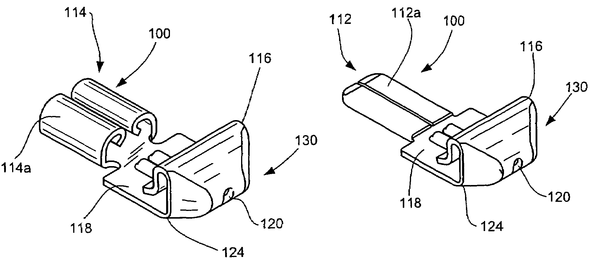
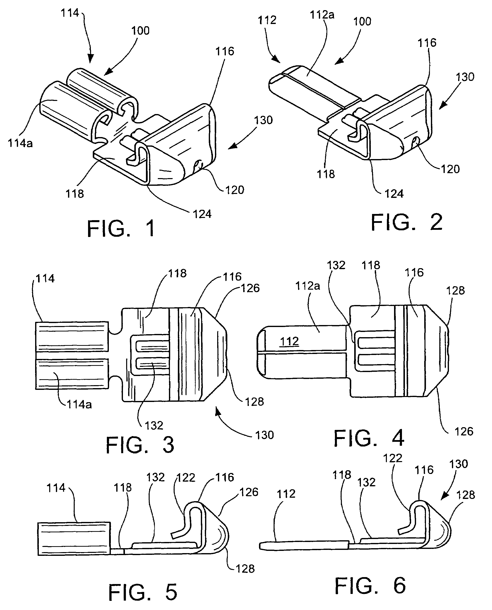
[0024]An electrical contact terminal 100 of the present invention is shown in the FIGS. 1-6. The contact terminal 100 may be a traditional male terminal 112 or a female terminal 114. These contact terminals are of the “push-in” variety and are often used in such electrical connectors as disconnects. The actual contact type can be formed in any well known configuration such as a spade, a ring, a ferrule or pin type contact. Alternate electrical connector component designs are also possible or such components may be employed in other types of electrical connectors such as an interconnect or a splice that is used to join a wire or cable to another or to an electrical device. The present invention is not limited to the type of electrical connector employed.

[0025]For simplicity of description, contact terminal 100 will be referred to where the components are identical with respect to male terminal 112 and female terminal 114.

[0026]In most electrical connector components of the type desc...


PUM


Abstract

A contact terminal is useful as an electrical disconnect. The contact terminal is generally of one-piece construction having a main body and a portion thereof cantilevered from this main body. This cantilevered portion is configured with a wire receiving apparatus so as to receive the wire therein and allow the wire to make both mechanical and electrical engagement with the contact terminal. The contact terminal is also configured with an embossment or stiffener adjacent the junction of the main body and the cantilevered portion so as to provide rigidity to the cantilevered portion when this portion is subject to a wire withdrawal force.

Description

CROSS-REFERENCE TO RELATED APPLICATIONS[0001]This application claims priority to U.S. Provisional Application No. 60 / 793,436, filed Apr. 20, 2006.FIELD OF THE INVENTION[0002]This invention pertains to electrical connector components in general and particularly to electrical contact terminals with or without dielectric housing such as those as can be used in disconnects to de-energize or isolate fluorescent lamps and ballasts for servicing.BACKGROUND OF THE INVENTION:[0003]Industry standards are oftentimes established as a means of insuring the safety of the installer and for the end-user. Presently, it is anticipated that the National Electric Code (NEC) will begin implementing regulations requiring all fluorescent luminaries to have a means of electrically isolating their components so as to increase the safety of working on them or replacing their parts in the field. This new provision is intended to make standard the ability to safely disconnect various electrical components from...

Claims


Application Information

Patent Timeline
Patent Type & Authority Patents(United States)
IPC IPC(8): H01R4/24
CPCH01R11/05H01R4/26H01R4/4818H01R11/28H01R4/48185
Inventor OSBORN, JR., ROBERT H.COLE, ANDREW C.BAKER, JAMES MICHAEL
Owner THOMAS & BETTS INT INC
Why Eureka
Try Eureka