GRA MEMS accelerometer

a technology of accelerometer and accelerometer body, applied in the direction of speed/acceleration/shock measurement, measurement devices, instruments, etc., can solve the problems of limiting the accuracy of scale factor and unbalanced mass, and achieve the effect of minimizing structural instability

Inactive Publication Date: 2009-01-06
CARDARELLI DONATO
View PDF6 Cites 3 Cited by
  • Summary
  • Abstract
  • Description
  • Claims
  • Application Information

AI Technical Summary

Benefits of technology

[0020]This invention also relates to monolithic constructions of the GRA to minimize structural instability. Because of this, the structure is electrically connected to ground.

Problems solved by technology

The accuracy and stability will be dependent on the accuracy and stability of the applied voltage and the actuator functionality, thereby limiting scale factor accuracy if only the voltage is measured.
Under acceleration, the unbalanced mass generates a torque that tends to rotate the gimbal about the OA.

Method used


Image

  • GRA MEMS accelerometer
  • GRA MEMS accelerometer
  • GRA MEMS accelerometer

Examples


Embodiment Construction

[0039]The GRA is similar in operation to the PIGA. By understanding the PIGA, the description of the POGA is simplified.

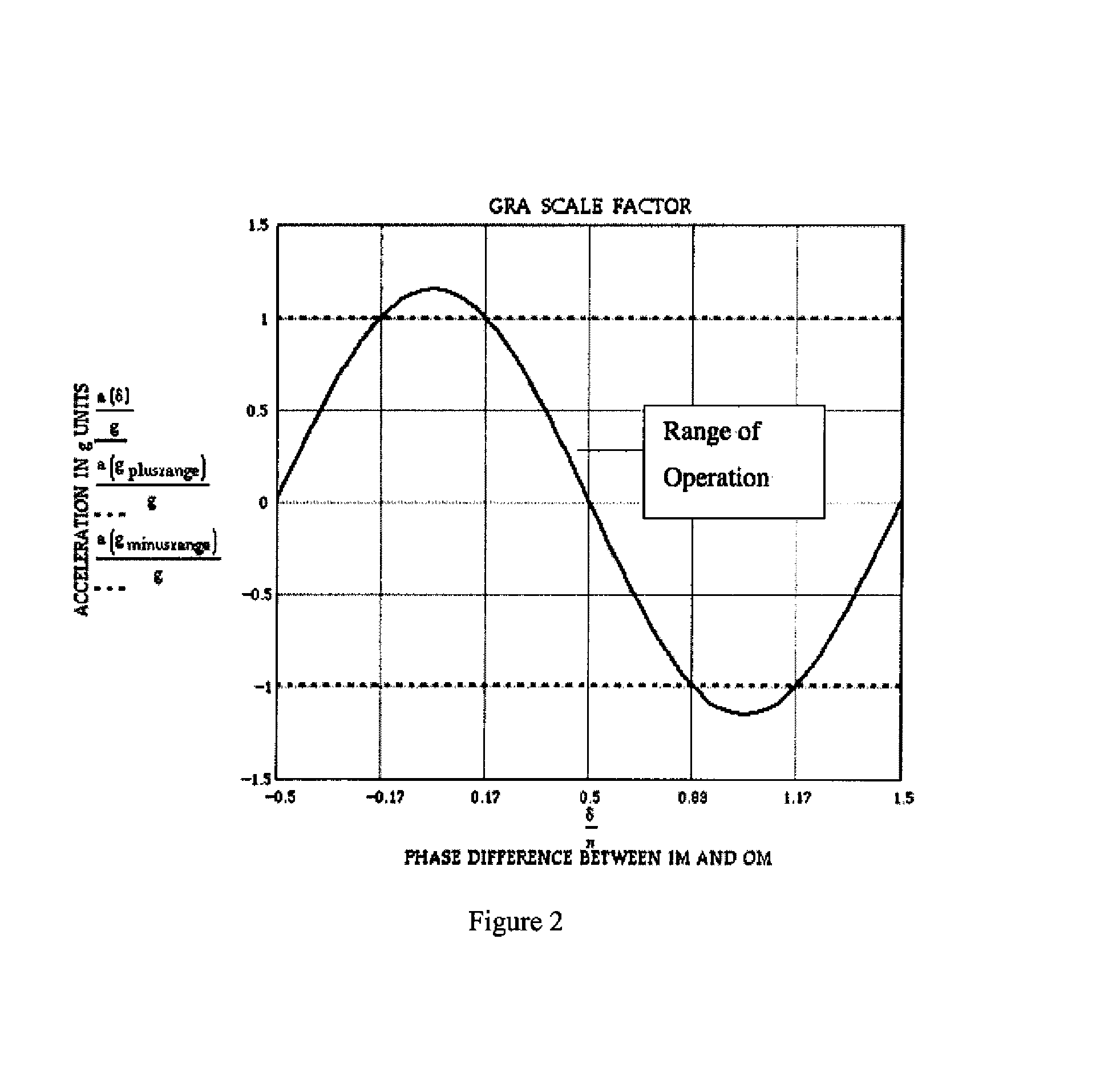
[0040]Like the PIGA, the GRA is based on the use of a stable gyroscope. However, because the rotor and Servo Member in the GRA are oscillatory, the measurement and control of their amplitudes bypasses the instability in the actuators and the voltages applied. Therefore a stable and accurate scale factor will be obtained.

GRA Description / Principle of Operation

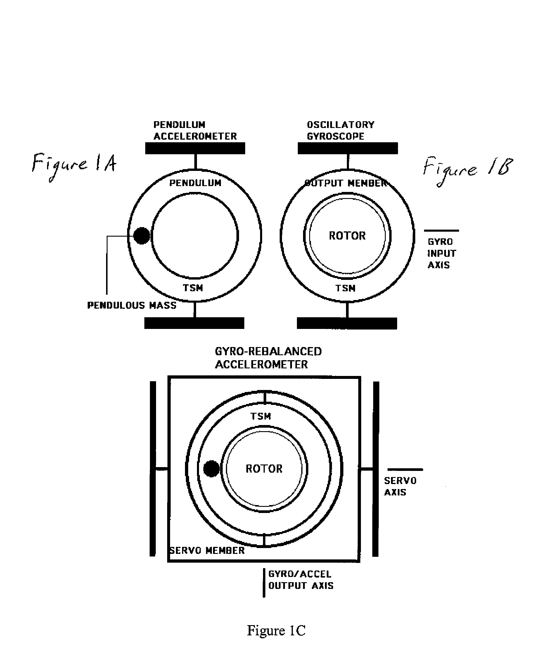
[0041]The GRA is a planar device with two oscillating members and a pendulum. FIGS. 1A-1C show how the gyroscope and pendulum are combined in one instrument. The simple pendulum accelerometer, FIG. 1A, contains an annular disk with a pendulous mass. The disk is attached to the substrate with two in-line torsional flexures. The gyroscope, FIG. 1B, contains a rotor in the center of a balanced annular disk. The disk is also attached to the substrate with two, in-line torsional flexures. The gyro is operated by osci...


PUM


Abstract

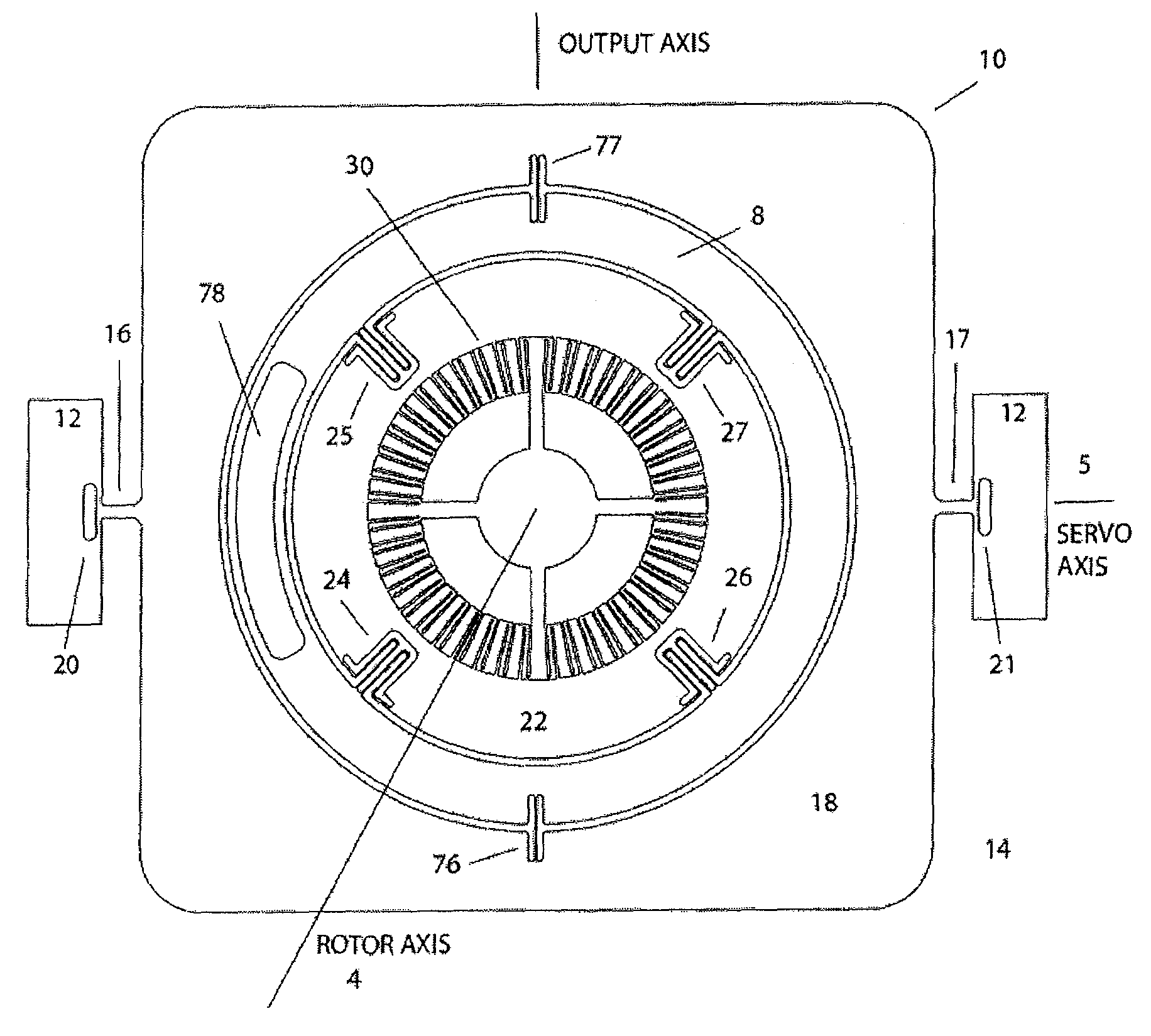
An accelerometer that lies generally in a plane, for detecting acceleration along an input axis. There is a substrate, a generally planar Servo Member (SM) flexibly coupled to the substrate such that it is capable of oscillatory motion about a servo axis that lies in the plane, a generally planar Torque Summing Member (TSM) coplanar with and flexibly coupled to the SM such that the TSM is capable of rotary motion relative to the SM about an output axis that is in the plane and orthogonal to the servo axis, wherein the TSM is mass-imbalanced relative to the output axis, and a generally planar rotor coplanar with and flexibly coupled to the TSM such that it is capable of rotary oscillatory motion relative to the TSM about a rotor axis that is orthogonal to the plane of the members. There are drives for oscillating the rotor about the rotor axis and for oscillating the SM about the servo axis. Output sensors detect oscillation of the rotor about the rotor axis and of the SM about the servo axis. Output sensors detect rotation of the TSM about the output axis.

Description

CROSS REFERENCE TO RELATED APPLICATION[0001]This application claims priority of provisional application Ser. No. 60 / 702,422 filed on Jul. 26, 2005, the disclosure of which is incorporated herein by reference.STATEMENT REGARDING FEDERALLY SPONSORED RESEARCH[0002]This invention was made with government support under contract number HQ0006-05-C-2718 issued by the MDA. The government has certain rights in this invention.FIELD OF THE INVENTION[0003]This invention relates to accelerometer designs.BACKGROUND OF THE INVENTION[0004]Closed loop MEMS pendulous accelerometers typically use torque rebalance with a voltage-controlled capacitive actuator to hold the pendulum at null. Assuming the actuator is stable, the voltage applied is proportional to acceleration. The accelerometers are calibrated to obtain the scale factor (acceleration to voltage proportionality). In this implementation, the torque applied is not measured directly. The accuracy and stability will be dependent on the accuracy...

Claims


Application Information

Patent Timeline
Patent Type & Authority Patents(United States)
IPC IPC(8): G01P15/14
CPCG01P15/0802G01P15/125G01P15/13G01P15/14
Inventor CARDARELLI, DONATO
Owner CARDARELLI DONATO
Why Eureka
Try Eureka