
Input apparatus, computer apparatus, method for identifying input object, method for identifying input object in keyboard, and computer program

a technology of input objects and keyboards, applied in the field of input apparatuses, computer apparatuses methods for identifying input objects in keyboards, etc., can solve the problem of frequent errors in inputs, and achieve the effect of reducing or preventing incorrect inputs

Inactive Publication Date: 2009-01-13
LENOVO PC INT
View PDF19 Cites 298 Cited by
  • Summary
  • Abstract
  • Description
  • Claims
  • Application Information

AI Technical Summary

Benefits of technology

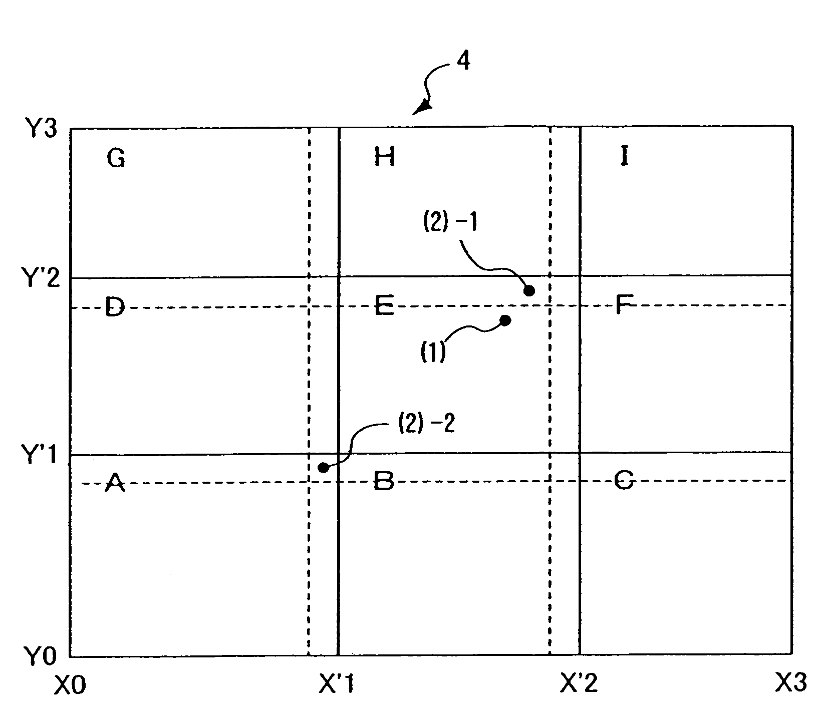
[0021]The input device according to this invention can vary the identification area for a certain key based on the location at which the first preceding touch input is made. Thus, incorrect inputs can be reduced or prevented as described with reference to FIGS. 8 and 9.
[0022]In the input device according to the invention, the area setting unit can vary the identification area for a key corresponding to the identification area that includes the location at which the first touch input is made. This is done for reducing or preventing incorrect inputs due to the second touch input following the first input on the key in question. Once the identification area is established, touch inputs at any location within the identification area are recognized as inputs on the same key.
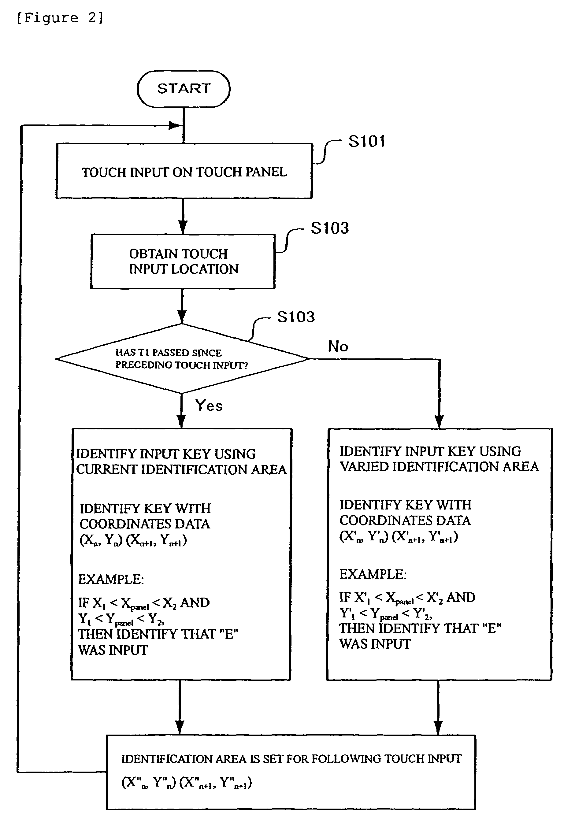
[0024]Thus, the object of the input device of this invention is to reduce or prevent incorrect inputs due to the first and second touch inputs performed successively. Therefore, this invention can be activated for a predetermined period between the two inputs that permits the two inputs to be varied as successive inputs. Then, the input device according to this invention can allow the identification area to be varied for the predetermined period after the preceding first touch input. The predetermined period will be derived from analysis of actual touch inputs.
[0034]In the method according to this invention for identifying a target key for an input, when the following touch input is made within a predetermined period after the preceding touch input, the target key for the following touch input is identified based on the new identification area formed by the boundaries varied according to the preceding touch input. In this way, incorrect inputs are reduced or prevented.

Problems solved by technology

Thus, incorrect inputs frequently occur especially on adjacent keys.

Method used


Image

  • Input apparatus, computer apparatus, method for identifying input object, method for identifying input object in keyboard, and computer program
  • Input apparatus, computer apparatus, method for identifying input object, method for identifying input object in keyboard, and computer program
  • Input apparatus, computer apparatus, method for identifying input object, method for identifying input object in keyboard, and computer program

Examples


Embodiment Construction

[0047]Now, the invention will be described according to an embodiment.

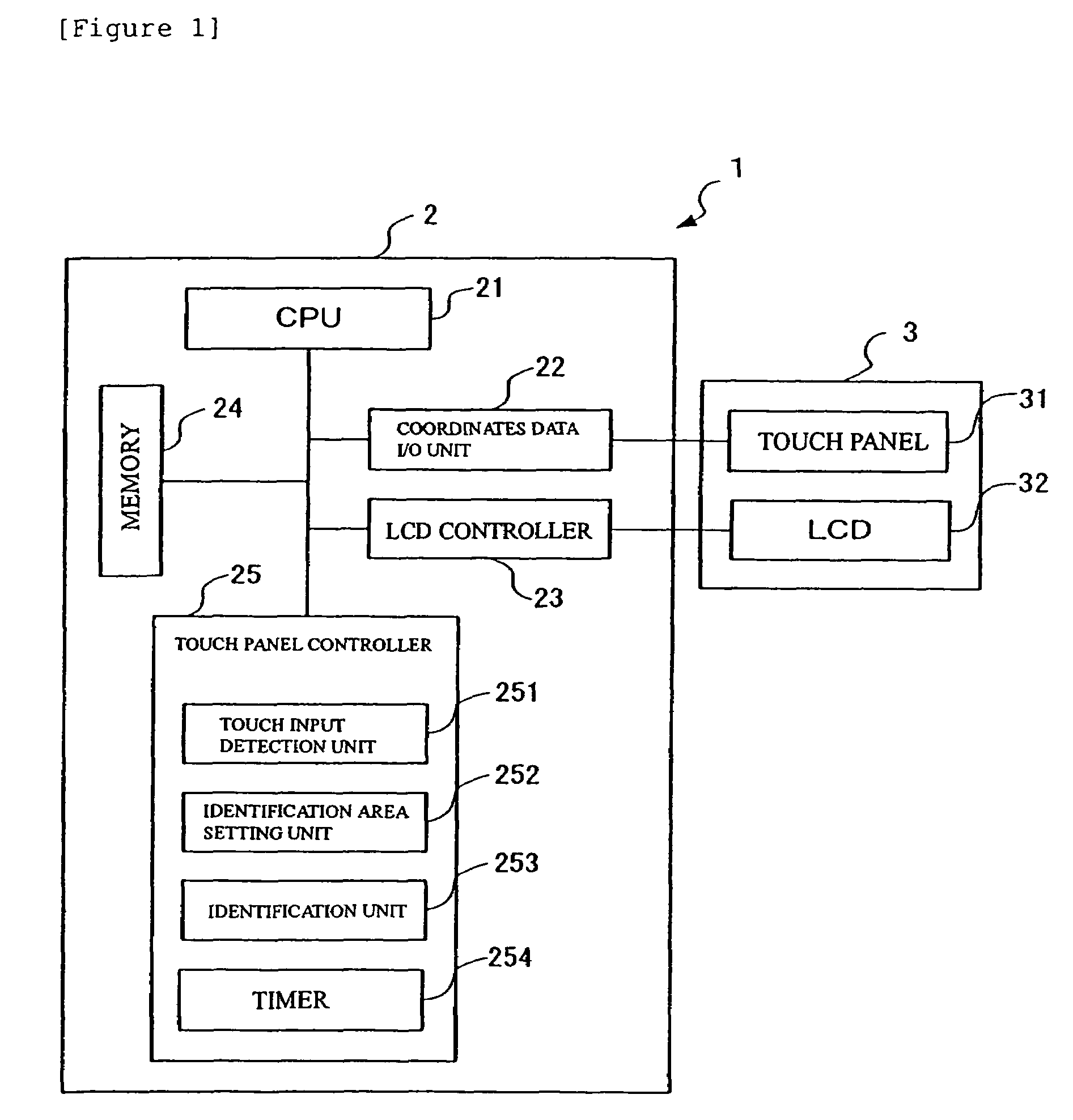
[0048]FIG. 1 is a block diagram illustrating a configuration of a computer device 1 according to the embodiment. As shown in FIG. 1, the computer device 1 is basically configured with a computer device main body 2 and a display unit 3.

[0049]The computer device main body 2 includes a CPU 21, a coordinates data acquisition unit 22, an LCD controller 23, memory 24, and a touch panel controller 25.

[0050]The CPU 21 is a central processing unit for controlling the entire computer device 1, and it is responsible for processing touch input performed on a touch panel 31 and displaying images' on an LCD 32 based on programs stored in the memory 24.

[0051]The coordinates data acquisition unit 22 detects data resulting from a user's touch input onto the touch panel 31 and converts the data into digital coordinates data.

[0052]The LCD controller 23 reads out image data written by the CPU 21 in image memory (not shown) and output...


PUM


Abstract

A method, computer program product, and device for identifying a target key for a touch input are provided. The method, computer program product, and device provide for detecting a first location at which a first touch input is made, determining a first identification area that includes the first location at which the first touch input is made, obtaining a relative location of the first touch input in the first identification area, detecting a second location at which a second touch input following the first touch input is made, and identifying a target key for the second touch input based on the relative location and a distance between the first and second locations.

Description

FIELD OF THE INVENTION[0001]This invention relates to a method for preventing incorrect inputs on a software-keyboard that uses a touch panel.BACKGROUND ART[0002]Software keyboards are used to display a keyboard arrangement on a screen of an LCD (Liquid Crystal Display) panel having touch panel functions and enable input of characters on behalf of a mechanical keyboard by using a coordinates detection function of the touch panel.[0003]Unlike common hardware keyboards that involve strokes in the up-and-down (pressing) direction, software keyboards rely only on display on a flat screen, wherein boundaries among adjacent keys cannot be recognized by mechanical projections and depressions. Thus, incorrect inputs frequently occur especially on adjacent keys.[0004]Methods for preventing or reducing such incorrect inputs have been proposed, such as the method of Japanese Patent Laid-Open No. 11-53093. The Japanese Patent Laid-Open No. 11-53093 proposes an input device comprising: a display...

Claims


Application Information

Patent Timeline
Patent Type & Authority Patents(United States)
IPC IPC(8): G09G5/00G06F3/048
CPCG06F3/04886G06F3/0418G06F3/03
Inventor YANAGISAWA, TAKASHI
Owner LENOVO PC INT
Learn More