
Clock model for formal verification of a digital circuit description

a clock model and digital circuit technology, applied in the field of digital circuit design analysis, can solve the problems that the sole use of highly detailed simulation and modeling cannot be used to investigate all possible errors at all times for all states of a circuit, and the verification process itself is a huge and complex task, so as to reduce or eliminate inaccuracies and other issues

Active Publication Date: 2009-02-03
SIEMENS PROD LIFECYCLE MANAGEMENT SOFTWARE INC
View PDF0 Cites 5 Cited by
  • Summary
  • Abstract
  • Description
  • Claims
  • Application Information

AI Technical Summary

Benefits of technology

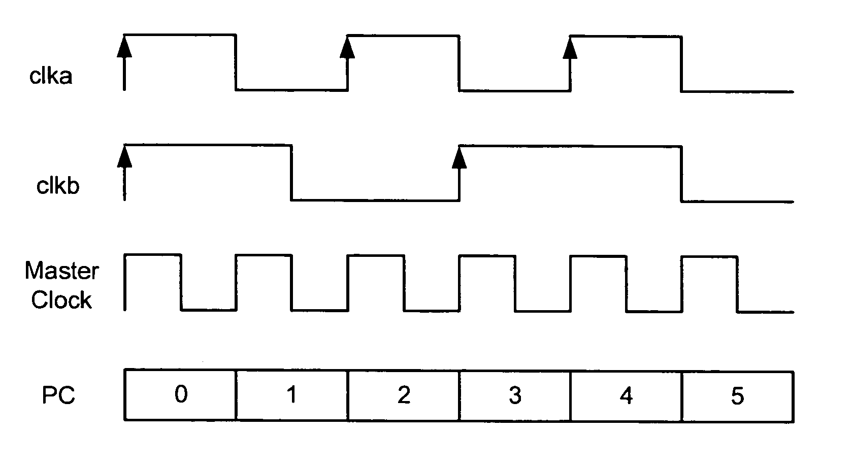
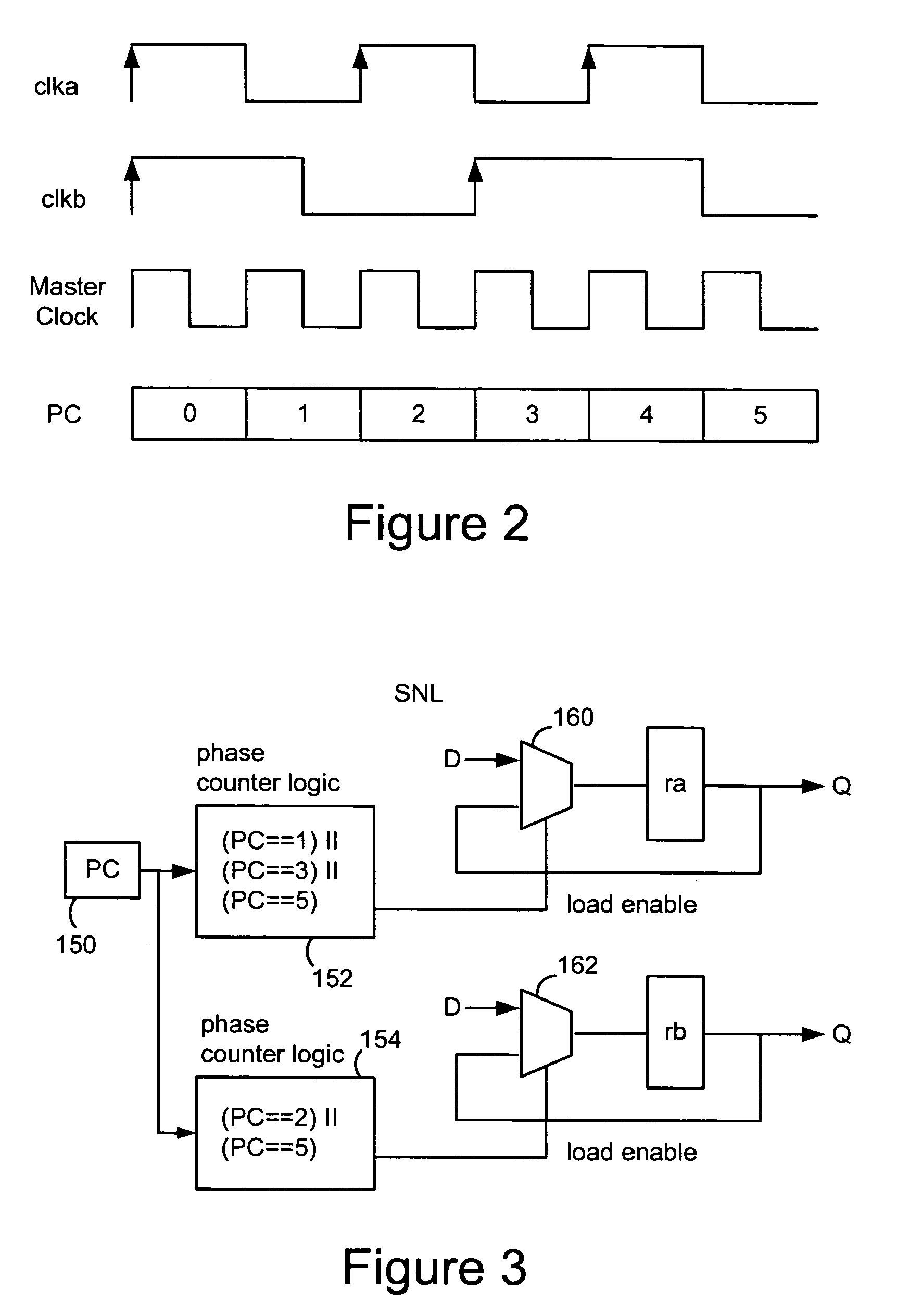
[0007]A preferred embodiment of the invention uses an edge clock model to capture states from a logic-level simulation of a circuit description for formal verification of a circuit description. The states are captured at clock edges, or transitions, according to an edge clock model based on a clock specification for the circuit description. The captured states can be used in verification or for other aspects of testing, simulation or analysis. This approach helps to reduce or eliminate inaccuracies and other issues with other clock models such as a phase clock model.

Problems solved by technology

Due to the extremely large size of many of today's circuits (e.g., millions of transistors) and the enormously complex behavior of physical systems modeling, the sole use of highly detailed simulation and modeling can not be used to investigate all possible errors at all times for all states of a circuit.
However, determining, identifying, managing and searching states during verification is, itself, a huge and complex task.
One problem with accurately obtaining state information for formal verification is trying to model the clock specification of a circuit description.

Method used


Image

  • Clock model for formal verification of a digital circuit description
  • Clock model for formal verification of a digital circuit description
  • Clock model for formal verification of a digital circuit description

Examples


Embodiment Construction

[0007]A preferred embodiment of the invention uses an edge clock model to capture states from a logic-level simulation of a circuit description for formal verification of a circuit description. The states are captured at clock edges, or transitions, according to an edge clock model based on a clock specification for the circuit description. The captured states can be used in verification or for other aspects of testing, simulation or analysis. This approach helps to reduce or eliminate inaccuracies and other issues with other clock models such as a phase clock model.

[0008]In one embodiment the invention provides a method for performing a formal verification of a circuit description, the method comprising: capturing state information by using clock edges from clock signals defined in the circuit description; and using the captured states in the formal verification.

[0009]In one embodiment, a phase clock model can be used in addition to the edge clock model. In another embodiment, the ...


PUM


Abstract

An edge clock model is used to capture states from a logic-level simulation of a circuit description. The states are captured at clock edges, or transitions, according to an edge clock model based on a clock specification for the circuit description. The captured states and associated attributes are used in formal verification of the circuit description. This approach helps to reduce or eliminate inaccuracies and other issues with other clock models such as a phase clock model. In one embodiment, a phase clock model can be used in addition to the edge clock model. In another embodiment, the edge clock states can be used to generate states according to different clock models, such as the phase clock model.

Description

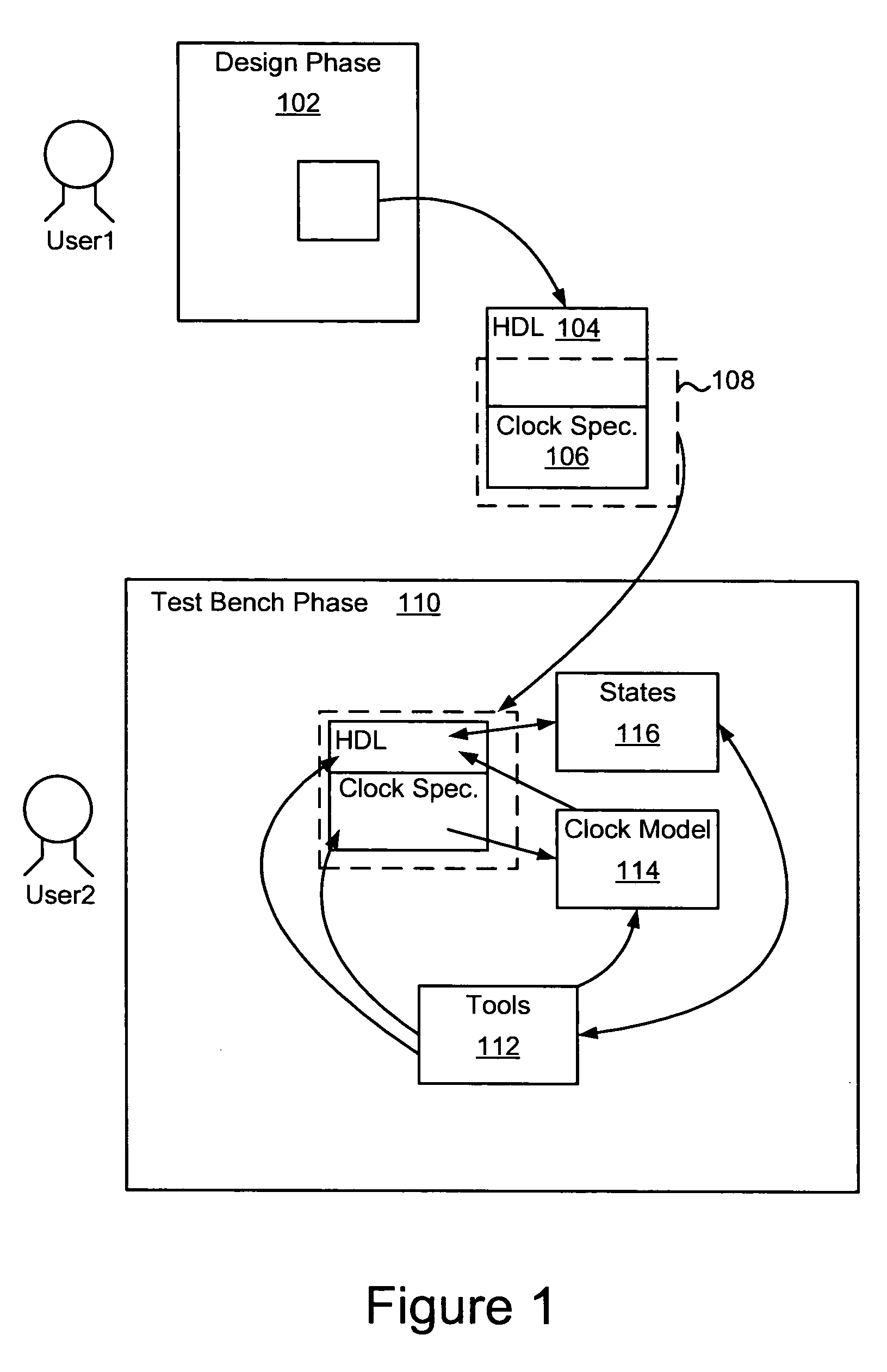
BACKGROUND OF THE INVENTION[0001]This invention relates in general to analysis of digital circuit designs and more specifically to a system for modeling clocks during digital circuit design verification.[0002]Today's approaches to simulation, testing and verification of digital circuit designs typically use a hardware design language (HDL) description of a circuit, gate array or other electronic devices or components. Examples of HDLs include, e.g., Verilog, AHDL, VHDL, etc. Once an HDL description of the circuit exists the description can be used in test bench simulations and verification to determine whether the circuit design performs correctly.[0003]Simulations allow a circuit description to be modeled at a very detailed level. Digital logic errors, or “exceptions,” can be determined. Complex simulation and modeling also takes into account electrical, electromagnetic and other types of physical effects that could cause problems with the physical circuit once the circuit descript...

Claims


Application Information

Patent Timeline
Patent Type & Authority Patents(United States)
IPC IPC(8): G06F17/50G06F9/45
CPCG06F17/504G06F30/3323
Inventor SEAWRIGHT, JAMES ANDREW GARRARDLEVITT, JEREMY RUTLEDGEGAUTHRON, CHRISTOPHE
Owner SIEMENS PROD LIFECYCLE MANAGEMENT SOFTWARE INC
Learn More