ARC baffle, and ARC chute assembly and electrical switching apparatus employing the same

a technology of electrical switching apparatus and arc chute, which is applied in the direction of contact mechanisms, high-tension/heavy-dress switches, air-break switches, etc., can solve the problems of undesirable flow of electrical current, vaporization or sublimation of the contact material itself, and the circuit breaker designer

Active Publication Date: 2009-02-10
EATON INTELLIGENT POWER LTD
View PDF11 Cites 41 Cited by
  • Summary
  • Abstract
  • Description
  • Claims
  • Application Information

AI Technical Summary

Problems solved by technology

The arc provides a means for smoothly transitioning from a closed circuit to an open circuit, but produces a number of challenges to the circuit breaker designer.
Among them is the fact that the arc results in the undesirable flow of electrical current through the circuit breaker to the load.
Additionally, the arc, which extends between the contacts, often results in vaporization or sublimation of the contact material itself.
Additionally, along with the generation of the arc itself, ionized gases, which can cause excessive heat and additional arcing and, therefore, are harmful to electrical components, are formed as a byproduct of the arcing event.

Method used


Image

  • ARC baffle, and ARC chute assembly and electrical switching apparatus employing the same
  • ARC baffle, and ARC chute assembly and electrical switching apparatus employing the same
  • ARC baffle, and ARC chute assembly and electrical switching apparatus employing the same

Examples


example 1

[0059]It will be appreciated that the baffle mount 288′ preferably comprises one single component (not shown), wherein the generally planar members 290,290′ of the baffle mount 288′ are made (e.g., without limitation, molded) from one single piece of material, as opposed to comprising two separate components as shown and described with respect to FIG. 9.

example 2

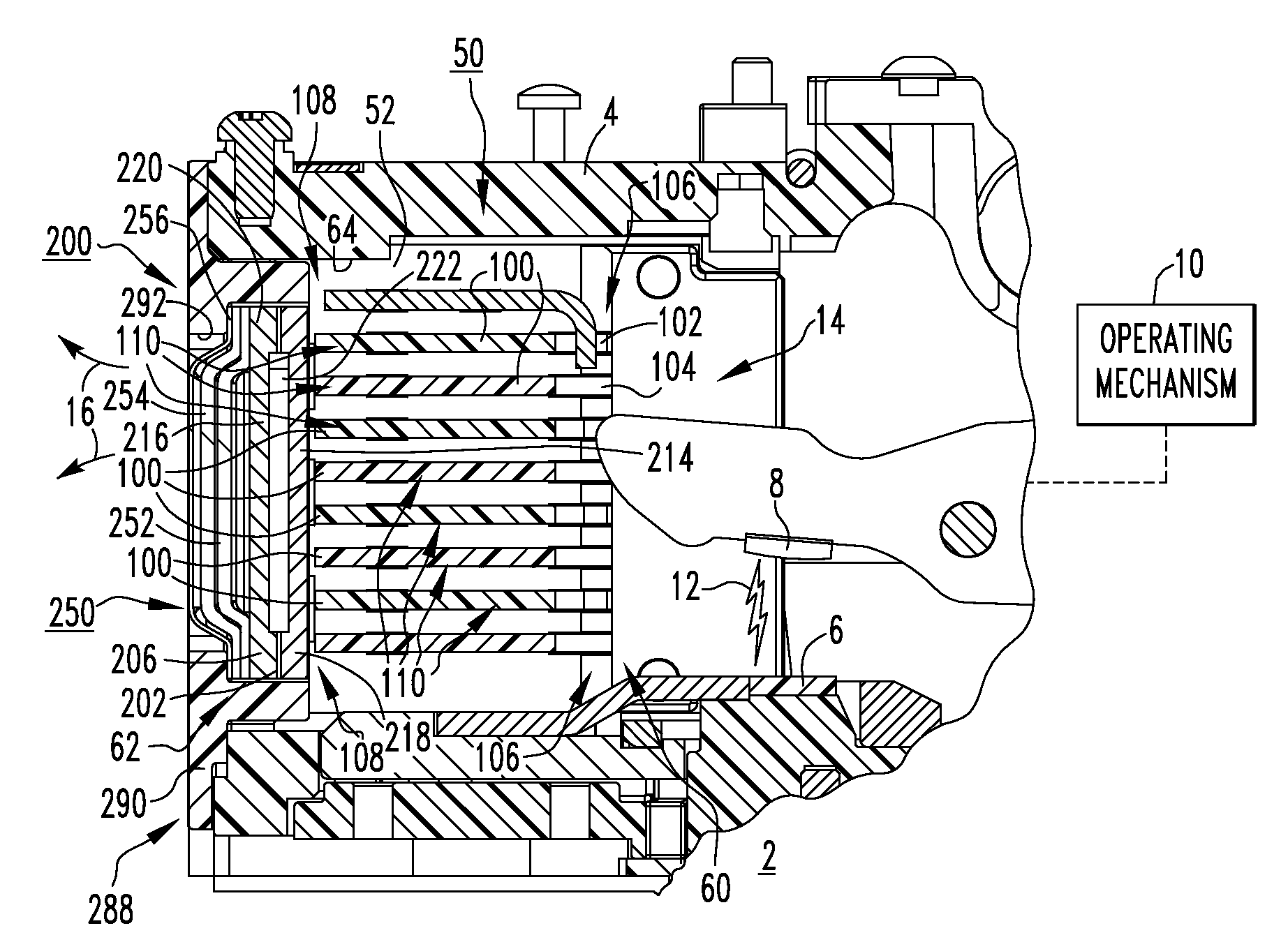
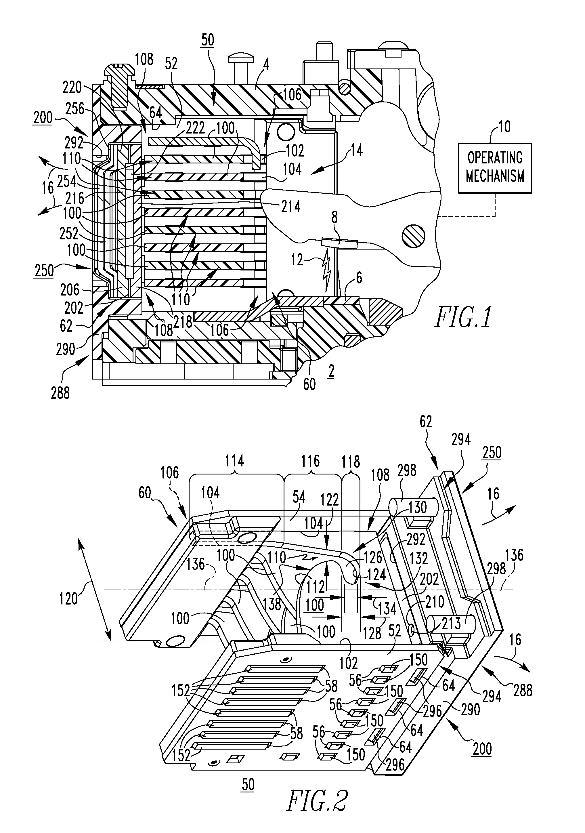
[0060]The filter assemblies 250 (FIG. 6), 250′ (FIG. 9) of the arc baffle 200 (FIG. 6), 200′ (FIG. 9) can employ any known or suitable number and type (e.g., without limitation, substantially flat; formed or “cupped”) of filter elements 252,254,256 (FIG. 6), 252′,254′,256′ (FIG. 9), with or without spacer(s) 263 (FIG. 9).

example 3

[0061]The arc baffle 200 (FIG. 6), 200′ (FIG. 9) can employ the baffle mount 288 (FIG. 6), 288′ (FIG. 9) without the filter assembly 250 (FIG. 6), 250′ (FIG. 9), and without the first and second baffle members 202,206. Under such circumstances, the baffle mount 288 (FIG. 6), 288′ (FIG. 9) serves as the sole baffle member for facilitating the discharge of the ionized gases 16 (FIGS. 1, 2 and 5) from the arc chute assembly 50.


PUM


Abstract

An arc baffle for an arc chute assembly of a circuit breaker includes a first baffle member disposed at or about the second end of the arc chute assembly and including a plurality of first venting holes, a second baffle member including a plurality of second venting holes and being coupled to and disposed opposite from the first baffle member, and a filter assembly disposed at or about the second baffle member and including a number of filter elements. The first and second venting holes of the first and second baffle members are offset to induce turbulent flow of ionized gases being discharged from the arc chute assembly. The filter elements of the filter assembly filter the turbulent flow. An arc chute assembly and an electrical switching apparatus are also disclosed.

Description

CROSS-REFERENCE TO RELATED APPLICATIONS[0001]U.S. patent application Ser. No. 11 / 553,670, filed Sep. 20, 2006, entitled “ARC PLATE, AND ARC CHUTE ASSEMBLY AND ELECTRICAL SWITCHING APPARATUS EMPLOYING THE SAME”; and U.S. patent application Ser. No. 11 / 533,646, filed Sep. 20, 2006 entitled “GASSING INSULATOR, AND ARC CHUTE ASSEMBLY AND ELECTRICAL SWITCHING APPARATUS EMPLOYING THE SAME”, which are hereby incorporated herein by reference.BACKGROUND OF THE INVENTION[0002]1. Field of the Invention[0003]The invention relates generally to electrical switching apparatus and, more particularly, to arc baffles for the arc chute assemblies of electrical switching apparatus, such as circuit breakers. The invention also relates to arc chute assemblies for electrical switching apparatus. The invention further relates to electrical switching apparatus employing arc chute assemblies.[0004]2. Background Information[0005]Electrical switching apparatus, such as circuit breakers, provide protection for ...

Claims


Application Information

Patent Timeline
Patent Type & Authority Patents(United States)
IPC IPC(8): H01H33/02
CPCH01H9/342H01H2009/365
Inventor POLLITT, WILLIAM C.SHEA, JOHN J.KOZAR, AARON T.WEISTER, NATHAN J.
Owner EATON INTELLIGENT POWER LTD
Why Eureka
Try Eureka