Balloon dilation catheter having transition from coaxial lumens to non-coaxial multiple lumens

a balloon dilation catheter and multiple lumen technology, which is applied in the field of balloon dilation catheters and balloon dilation catheters, can solve the problems of poor trackability of catheter inflation/deflation time performance, increased time required for balloon inflation and deflation, and suffered from the effect of inflation/deflation performan

Active Publication Date: 2009-03-10
BARD PERIPHERAL VASCULAR
View PDF16 Cites 47 Cited by
  • Summary
  • Abstract
  • Description
  • Claims
  • Application Information

AI Technical Summary

Benefits of technology

[0011]The present invention disclosed and claimed herein comprises, in another aspect thereof, a shaft for a balloon dilation catheter to be utilized with a guidewire. The shaft comprises a shaft proximal portion, a shaft distal portion, and a shaft transitional portion disposed therebetween. Each of the proximal, distal and transitional shaft portions has a proximal end and a distal end. An outer tubular member having a bore extends from the proximal end of the shaft proximal portion to the distal end of the shaft transitional portion. At least one distal tubular member, each having a bore, extends from a starting point disposed within the shaft transitional portion to the distal end of the shaft distal portion. The portions of the distal tubular members extending between the starting point and the distal end of the shaft transitional portion are disposed within the bore of the outer tubular member. The bores of the distal tubular members define distal inflation / deflation lumens providing fluid communication between the shaft transition portion and the distal end of the shaft distal portion. A distal body encases the portions of the distal tubular members extending between the distal end of the shaft transitional portion and the distal end of the shaft distal portion. A guidewire tubular member having a bore extends from the proximal end of the shaft proximal portion to a point beyond the distal end of the shaft distal portion. The portion of the guidewire tubular member extending between the proximal end of the shaft proximal portion and the distal end of the shaft proximal portion is disposed coaxially within the bore of the outer tubular member, the portion of the guidewire tubular member extending between the distal tubular member starting point in the shaft transitional portion and the distal end of the shaft transitional portion is disposed within the bore of the outer tubular member alongside the distal tubular members, and the portion of the guidewire tubular member extending between the distal end of the shaft transitional portion and the distal end of the shaft distal portion is disposed in a multi-lumen arrangement with the distal tubular members and encased in the distal body. The bore of the guidewire tubular member defines a guidewire lumen for conveying a guidewire through the catheter shaft, and the space between the exterior of the guidewire tubular member and the interior of the outer tubular member defines a proximal inflation / deflation lumen providing fluid communication between the shaft proximal portion and the shaft transitional portion. A fluid-tight barrier is disposed within the proximal inflation / deflation lumen between the distal tubular member starting point in the shaft transitional member and the distal end of the shaft transitional member. The fluid-tight barrier blocks the flow of inflation fluid past the shaft transitional portion in the proximal inflation / deflation lumen, but allows the proximal inflation / deflation lumen to remain in fluid communication with the distal inflation / deflation lumens.
[0012]The present invention disclosed and claimed herein comprises, in a further aspect thereof, a shaft for a balloon dilation catheter to be utilized with a guidewire. The shaft comprises a shaft proximal portion wherein a guidewire tubular member having a first diameter and a first bore is disposed coaxially within an outer tubular member having a second diameter and a second bore. Connected to the distal end of the shaft proximal portion is a shaft transitional portion, wherein the guidewire tubular member is disposed within the bore of the outer tubular member and at least one distal tubular member having a third diameter and a third bore and not being present in the shaft proximal portion is also disposed within the bore of the outer tubular member, but not within the bore of the guidewire tubular member. Connected to the distal end of the shaft transitional portion is a shaft distal portion, wherein the guidewire tubular member and the distal tubular members are disposed in a side-by-side configuration and encased within a distal body, and the outer tubular member is not present. The bore of the guidewire tubular member defines a guidewire lumen for conveying a guidewire through the shaft, and the bores of the distal tubular members define distal inflation / deflation lumens providing fluid communication between the shaft transition portion and a distal end of the shaft distal portion. The space in the shaft proximal and transitional portions between the exterior of the guidewire tubular member and the interior of the outer tubular member defines a proximal inflation / deflation lumen providing fluid communication between a proximal end of the shaft proximal portion and the shaft transitional portion. A fluid-tight barrier is disposed within the proximal inflation / deflation lumen between a proximal end of the distal tubular members and a distal end of the outer tubular member. The fluid-tight barrier blocks the flow of inflation fluid past the shaft transitional portion in the proximal inflation / deflation lumen, but allows the proximal inflation / deflation lumen to remain in fluid communication with the distal inflation / deflation lumens.

Problems solved by technology

However, this migration towards catheters with smaller diameter, longer shafts has produced several new problems of its own.
First, catheter inflation / deflation time performance (i.e., the time required for inflation and deflation of the balloon) has suffered (i.e., increased) in the longer, smaller diameter catheters as frictional resistance to movement of the inflation fluid through the balloon inflation / deflation lumen(s) of the catheter becomes significant.
If the distal end of the catheter is not flexible enough, it may pull the guidewire out of position in the target lumen rather than follow it.
Unfortunately, while the inflation / deflation time performance of coaxial designs is considered good, the trackability of such designs tends to be poor because of the inherent stiffness of the full-diameter outer tubular member.
Thus, as the pressure rating of a coaxial style catheter increases to handle higher-pressure balloons, its trackability characteristics tend to become even worse.
These extruded shafts tend to have good trackability, especially when extruded from relatively soft plastic / resin, due to their lack of any internal structural stiffeners.
However, unless the lumen members are lined with a stronger material, the maximum balloon inflation pressure rating of extruded dual port shafts tends to be low compared to other designs.
For this reason, the use of extruded dual port catheters becomes more problematic as the working pressure of balloons rises.
Regrettably, while multi-lumen catheter shafts exhibit improved trackability over the coaxial designs previously described, both types of multi-lumen catheter shafts have inflation / deflation time performance that is inferior to the coaxial designs.
The reduced-size inflation / deflation lumens of the multi-lumen designs simply do not have fluid flow characteristics that are as good as the annular inflation / deflation lumen of the coaxial designs.
Accordingly, practitioners are currently forced to choose between balloon catheters which have good inflation / deflation performance but inferior trackability, good trackability but inferior inflation / deflation time performance, or a less-than-optimum compromise on both characteristics.

Method used


Image

  • Balloon dilation catheter having transition from coaxial lumens to non-coaxial multiple lumens
  • Balloon dilation catheter having transition from coaxial lumens to non-coaxial multiple lumens
  • Balloon dilation catheter having transition from coaxial lumens to non-coaxial multiple lumens

Examples


Embodiment Construction

[0021]The current invention is described below in greater detail with reference to certain preferred embodiments illustrated in the accompanying drawings.

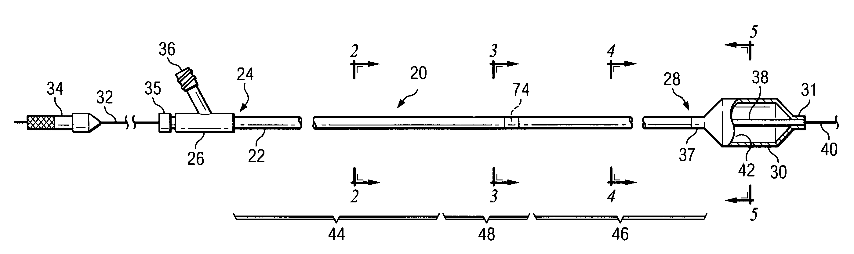
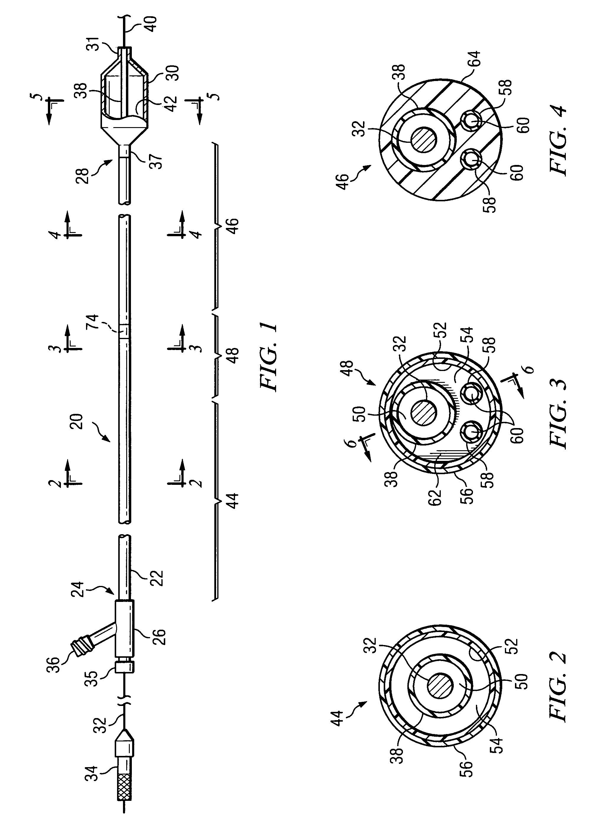
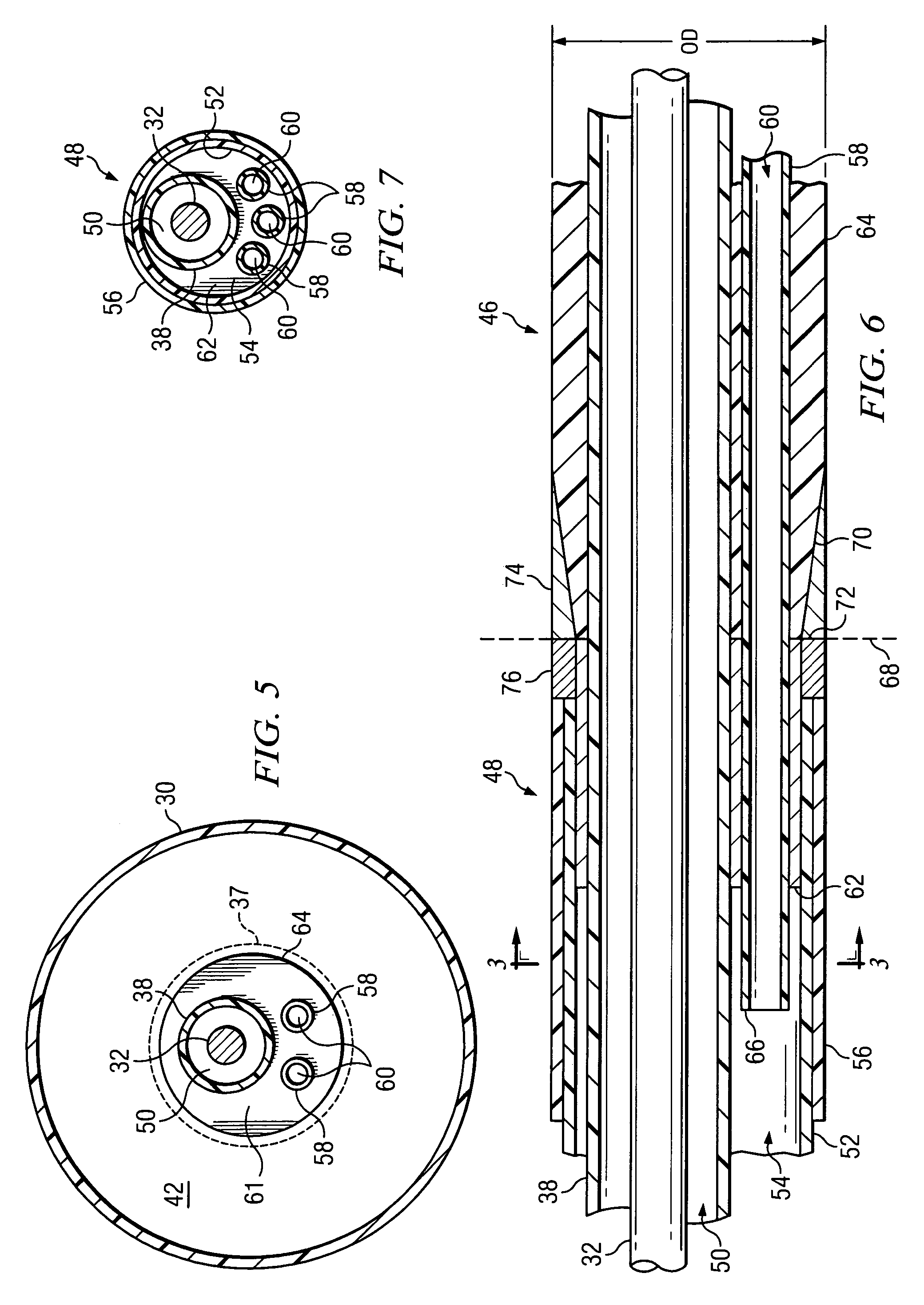
[0022]Referring now to FIG. 1, there is illustrated a balloon dilation catheter in accordance with one embodiment of the current invention. While this design may be used to make catheters of any diameter, it is particularly suitable for small diameter catheters, e.g., those having a diameter of 5 French or smaller. The catheter 20 includes a shaft 22 having a proximal end 24 that may be affixed to an access fitting 26 and a distal end 28 that may be affixed to a dilation balloon 30. As explained in further detail below, a plurality of tubular members disposed within the catheter 20 define a plurality of internal passageways, known as lumens. One such tubular member, the guidewire tubular member, extends longitudinally through the catheter from the access fitting 26 to the distal end 31 of the balloon 30. The guidewire tubular membe...


PUM

PropertyMeasurementUnit
pressuresaaaaaaaaaa
pressuresaaaaaaaaaa
lengthaaaaaaaaaa

Abstract

A shaft for a balloon dilation catheter comprises a proximal portion wherein a guidewire tubular member is disposed coaxially within an outer tubular member, a shaft transitional portion, wherein the guidewire member is disposed within the outer member, with at least one distal tubular member not present in the proximal portion, a shaft distal portion, wherein the guidewire member and the distal members are disposed side-by-side and encased within a distal body, and fluid-tight barrier within a proximal lumen blocking the flow of fluid in the proximal lumen, but allowing the proximal lumen to remain in fluid communication with a distal lumens.

Description

TECHNICAL FIELD OF THE INVENTION[0001]The current invention relates generally to angioplasty apparatus, and more specifically to balloon dilation catheters. In particular, it relates to a balloon dilation catheter having a first portion wherein the guidewire lumen and the balloon inflation / deflation lumen are coaxial and a second portion wherein the guidewire lumen and the balloon inflation / deflation lumens are non-coaxial.BACKGROUND OF THE INVENTION[0002]As treatment using balloon dilation catheters, for example, Percutaneous Transluminal Angioplasty Catheters (i.e., “PTACs”), has progressed into narrower and more remote vessels within the body, this has necessitated the use of catheters having correspondingly smaller shaft diameters and longer shaft lengths. However, this migration towards catheters with smaller diameter, longer shafts has produced several new problems of its own. First, catheter inflation / deflation time performance (i.e., the time required for inflation and defla...

Claims


Application Information

Patent Timeline
Patent Type & Authority Patents(United States)
IPC IPC(8): A61M29/00A61F2/958
CPCA61M25/0014A61M25/0043A61M25/1036A61M25/1034A61M25/104A61M25/0029Y10T29/49826A61M2025/0039A61M2025/004
Inventor PEPPER, LANNY R.
Owner BARD PERIPHERAL VASCULAR
Why Eureka
Try Eureka