
Storage battery device and power source apparatus comprising it

a storage battery and power source technology, applied in the direction of batteries, safety/protection circuits, primary cell maintenance/servicing, etc., can solve the problems of affecting the life of single cells, becoming difficult to grasp the definite temperature inside a single cell enough to shut off charging, and becoming impossible to stop charging on the basis of a single cell charge voltag

Active Publication Date: 2009-03-31
GS YUASA INT LTD
View PDF14 Cites 7 Cited by
  • Summary
  • Abstract
  • Description
  • Claims
  • Application Information

AI Technical Summary

Benefits of technology

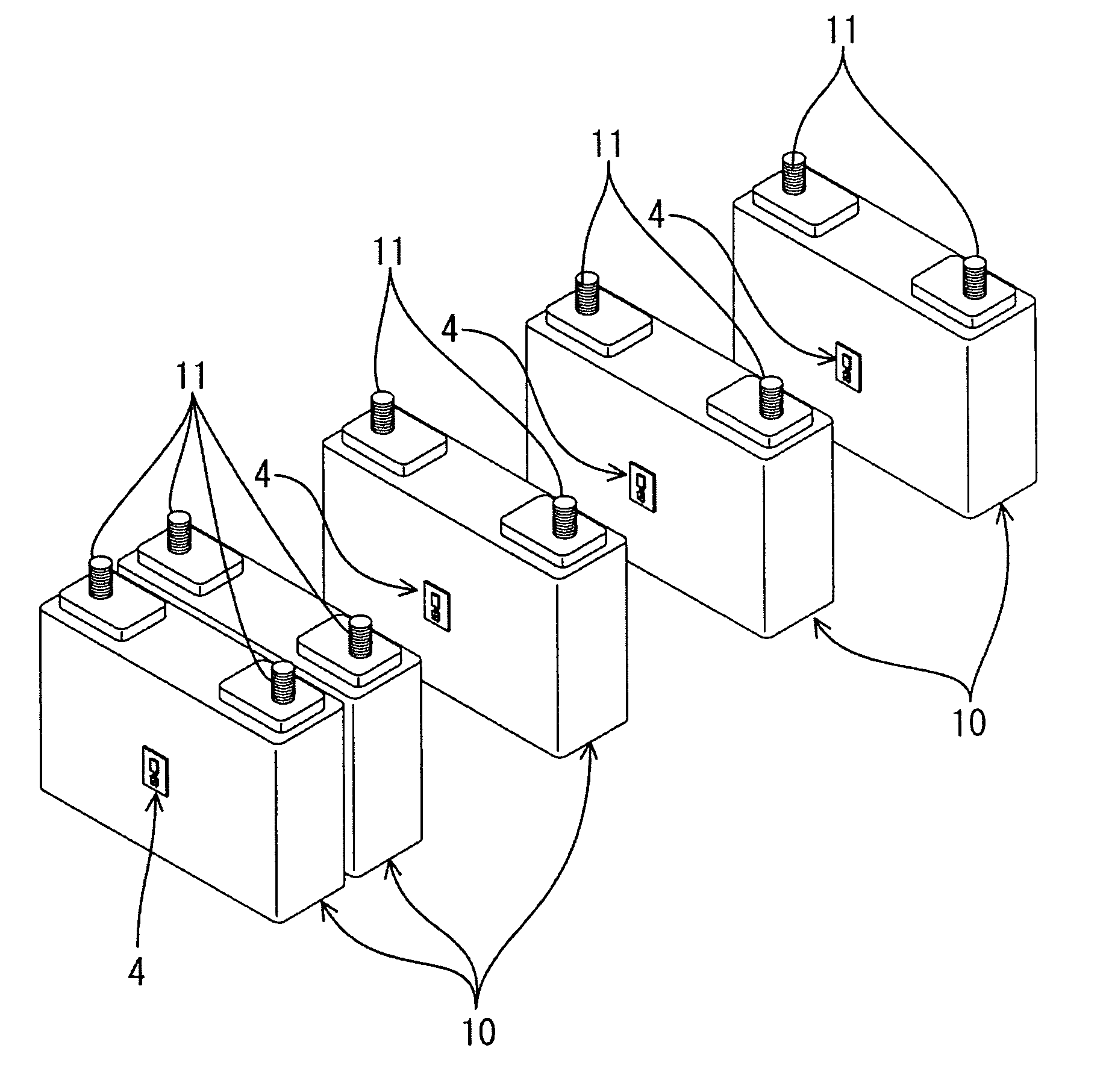
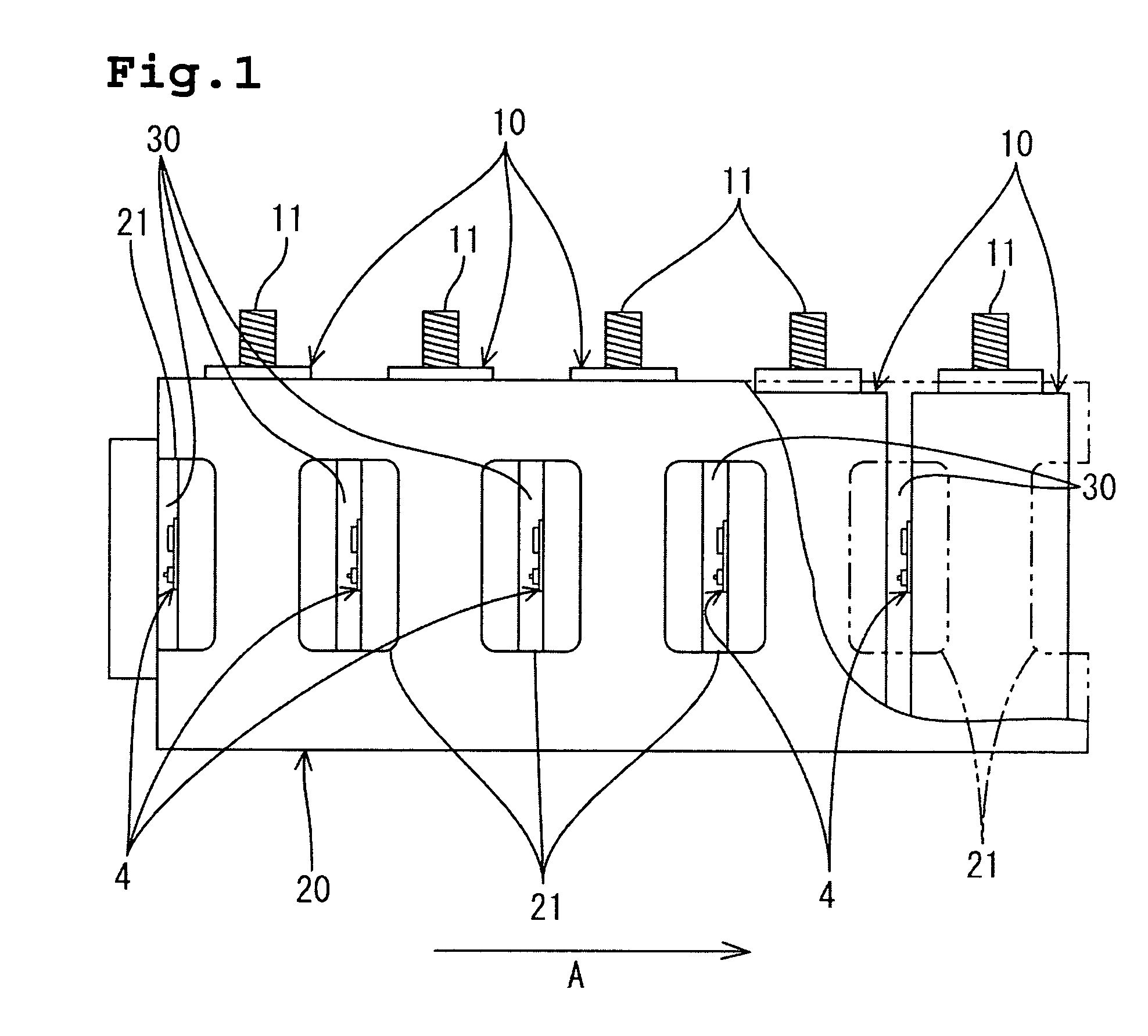
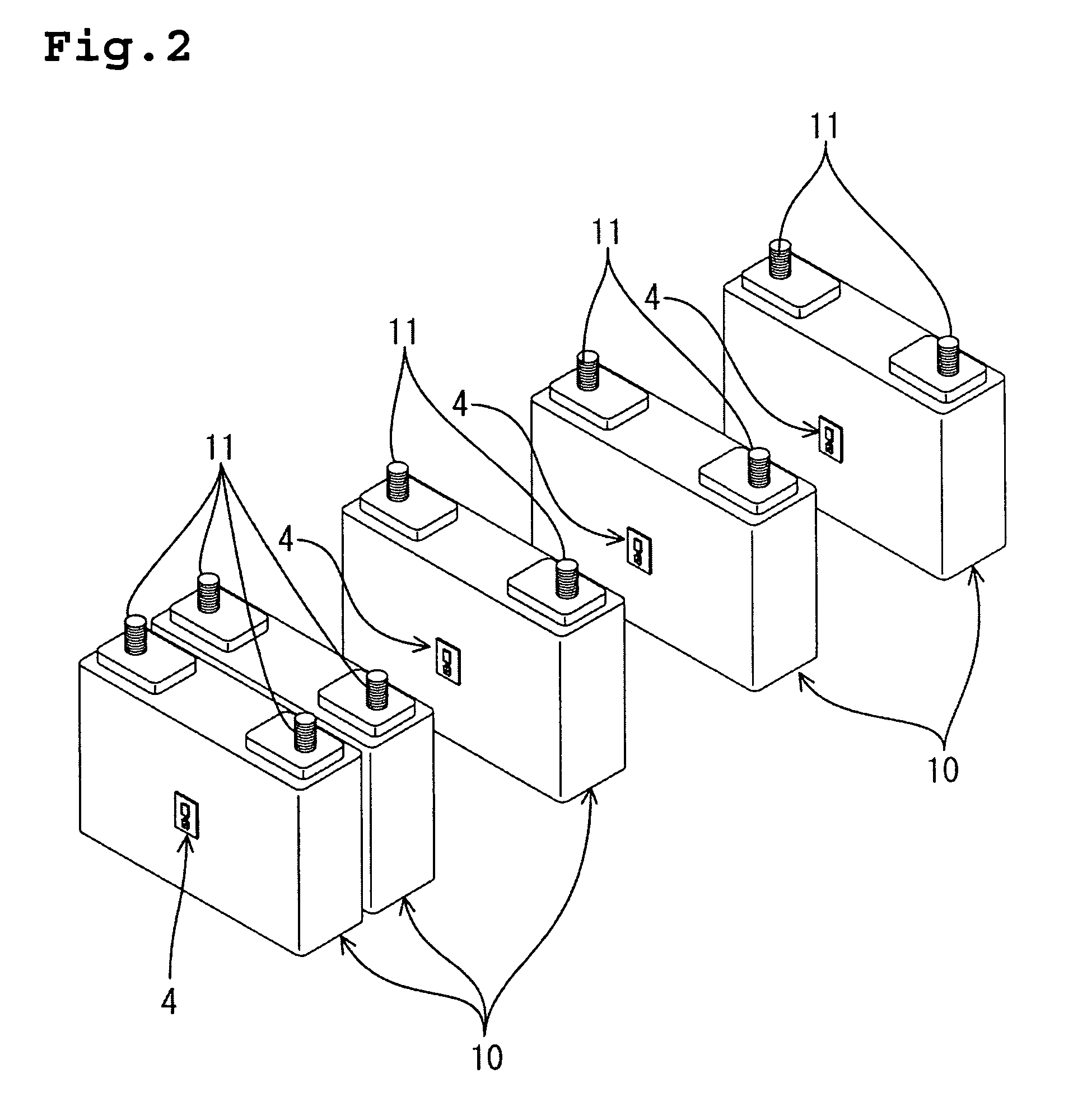
[0010]When single cells of a cuboid shape are used, it is preferable to arrange them in such a manner that side walls having the largest area are placed opposite each other and an element for detecting swelling are put almost on the center part of the side wall having the largest area. This is because the degree of transform by swelling becomes maximum at the center part of the side wall having the largest area of any other side walls in a single cell. Installing an element for detecting swelling at this position, therefore, makes transform by swelling much more detectable. In addition, regarding the shape of a single cell, an ellipsoidal shape, where the cross section is an elliptic cylindrical shape, is also applicable. In case of single cells of this shape, side walls with a major axis are placed opposite each other and an element for detecting swelling is put almost on the center part of the side wall. Thus, as described above, transform by swelling can be detected at this position with much more certainty.

Problems solved by technology

When a single cell is overcharged during the charging of such an assembled battery, the life of the single cell could be adversely affected.
When a single cell is overcharged, some changes are brought about in the single cell including an increase in charge voltage over a predetermined voltage; an abnormal rise in temperature; or transformation of the surface by swelling, which results when a polar plate inside the single cell swells and accordingly pushes out on the surface.
In case of any failure of the charging device, however, it becomes impossible to stop charging on the basis of a single cell charge voltage.
Accordingly, it becomes difficult to grasp the definite temperature inside a single cell enough to shut off charging.
According to this configuration, if a single cell is overcharged and then excess transformation by swelling occurs on the surface of the single cell, the switch will end up being pressed by the swollen single cell surface and this will lead to termination of charging.
However, these types of assembled batteries usually require a ventilation space between single cells to help dissipate the heat from them.
Therefore, the use of the above described configuration, where installation of the switch results in the need of a space between the inner wall of the container and each single cell, leads to an increase in size, and consequently concerns about a considerably large place for installation.

Method used


Image

  • Storage battery device and power source apparatus comprising it
  • Storage battery device and power source apparatus comprising it
  • Storage battery device and power source apparatus comprising it

Examples


second embodiment

[0034]A second embodiment in which the power supplying device of the present invention is embodied will be described with reference to FIG. 5. In this embodiment, regarding the identical portion as the first embodiment, overlapping description will be omitted with identical code appended.

[0035]In this embodiment, by contrast with the first embodiment, push button switches 71 with constant opened contact are used and connected in parallel each other and, in addition, a relay switch 63B with constant closed contact is used in the charge stop circuit 6.

[0036]According to this embodiment, when none of the single cells 10 are overcharged and has transformation by swelling, the push button switch 71 remains in the open position, and then since current is not passing into a relay coil 63A, power consumption can be reduced.

third embodiment

[0037]A third embodiment in which the power supplying device of the present invention is embodied will be described with reference to FIGS. 6 and 7. In this embodiment, regarding the identical portion as the first embodiment, overlapping description will be omitted with identical code appended and, in addition, description regarding similar action / effect is also omitted.

[0038]In this embodiment, the arrangement of the single cells 10 differs from that of the first embodiment, where the single cells 10 are set in line in the direction of depth, or one dimensional position (see FIG. 2). By contrast, this embodiment employs two dimensional position, where four single cells 10 are set in two lines in the direction of depth. In addition, on the center of the front wall of each single cell 10 which is placed in the backward position of the single cells 10 adjoining longitudinally, the circuit board 4 is fixed, where push button switches 41 are connected each other in series.

[0039]It is no...


PUM


Abstract

An assembled battery device comprising a plurality of single cells which are placed with a predetermined space between each of them and an element for detecting swelling is set in the predetermined space between the single cells and operates in accordance with the transformation of the single cells by swelling. Therefore, when a single cell swells and transforms, resulting from being overcharged, the element for detecting swelling is activated in accordance with such transformation and detects the state of overcharging.

Description

FIELD OF THE INVENTION[0001]The present invention relates to an assembled battery device comprising a plurality of single cells, and a power supplying device using this assembled battery device.BACKGROUND OF THE INVENTION[0002]In general, a secondary battery, which can be recharged and used repeatedly, is used as an assembled battery in which a plurality of single cells is assembled depending on the load. When a single cell is overcharged during the charging of such an assembled battery, the life of the single cell could be adversely affected. Therefore, it is necessary to prevent each single cell from being overcharged during the charging process.[0003]When a single cell is overcharged, some changes are brought about in the single cell including an increase in charge voltage over a predetermined voltage; an abnormal rise in temperature; or transformation of the surface by swelling, which results when a polar plate inside the single cell swells and accordingly pushes out on the surf...

Claims


Application Information

Patent Timeline
IPC IPC(8): H01M2/26H01M6/42H01M6/50H01M10/44H01M10/48H01M50/569H02J7/00
CPCH01M2/345H01M10/48H02J7/0026H01M2/0217H01M6/42H01M10/44H01M2200/20H02J7/0063H02J7/0013Y02E60/10H01M50/103H01M50/578H02J7/00302H02J7/00714H01M50/569
Inventor MASUDA, HIDEKITASAI, HIROSHINISHIYAMA, KOICHI
Owner GS YUASA INT LTD
Learn More