Vented valve

a valve body and valve body technology, applied in the field of valve body, can solve the problems of uneven and insufficient flow rate, unsatisfactory for many applications, and liquid flow,

Inactive Publication Date: 2009-04-07
FOODSERVICES BRAND GRP LLC (
View PDF29 Cites 75 Cited by
  • Summary
  • Abstract
  • Description
  • Claims
  • Application Information

AI Technical Summary

Problems solved by technology

Use of a conventional, unvented valve for dispensing liquid will result in liquid flow, if any, that is uneven and insufficient in terms of flow-rate as air must enter the container through the liquid flow passage.
Vented valves that allow air to flow into the container are known but have been found to be unsatisfactory for many applications.
In some cases, these vented valves rely on use of a vent-tube that extends deep into the container, and these tubes are not suitable for certain applications and also increase cost and are unsightly when visible in the container.
Known vented valves are overly complex and, thus, expensive due to material and assembly cost.
Also, these known valves often include a seal element that is common to the vent passage and the liquid flow passage and, the simultaneous opening of these passages often results in poor results, especially when dispensing liquid from a pressurized container.

Method used


Image

  • Vented valve
  • Vented valve
  • Vented valve

Examples


Embodiment Construction

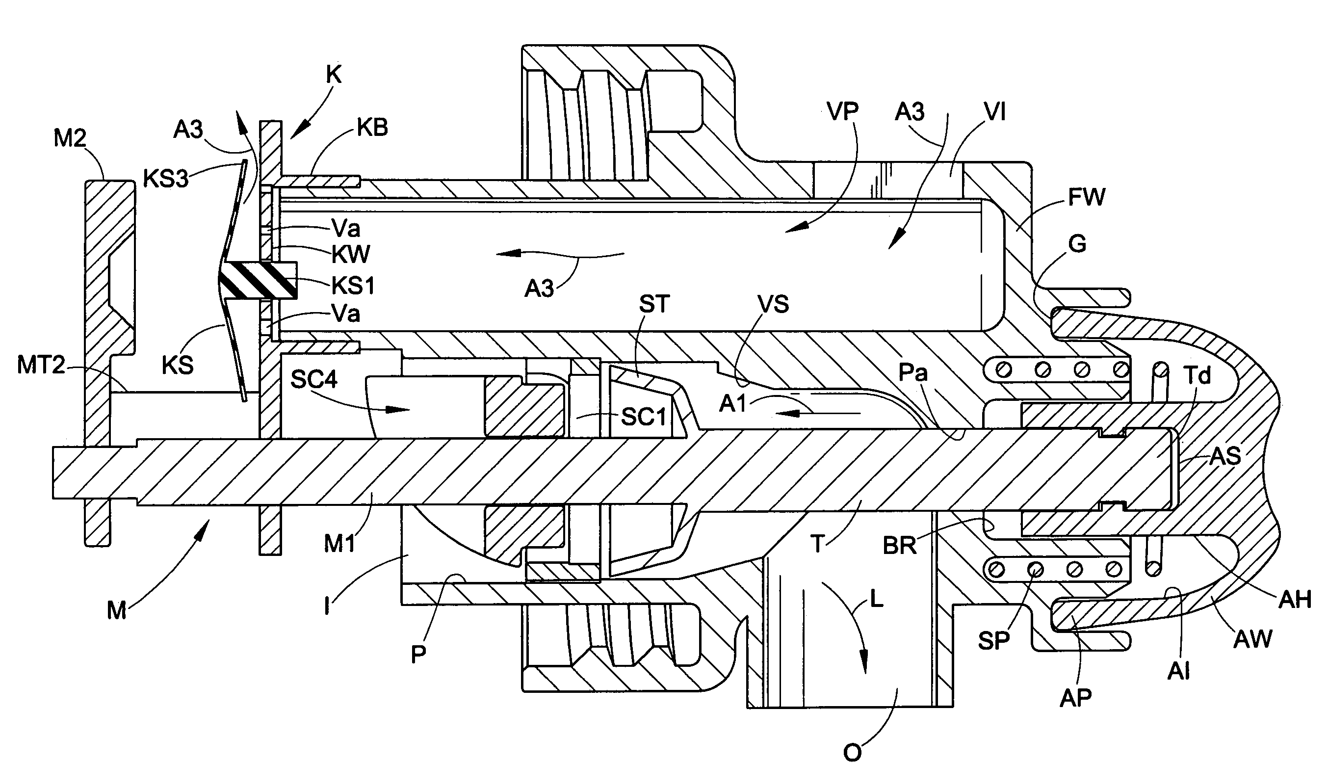
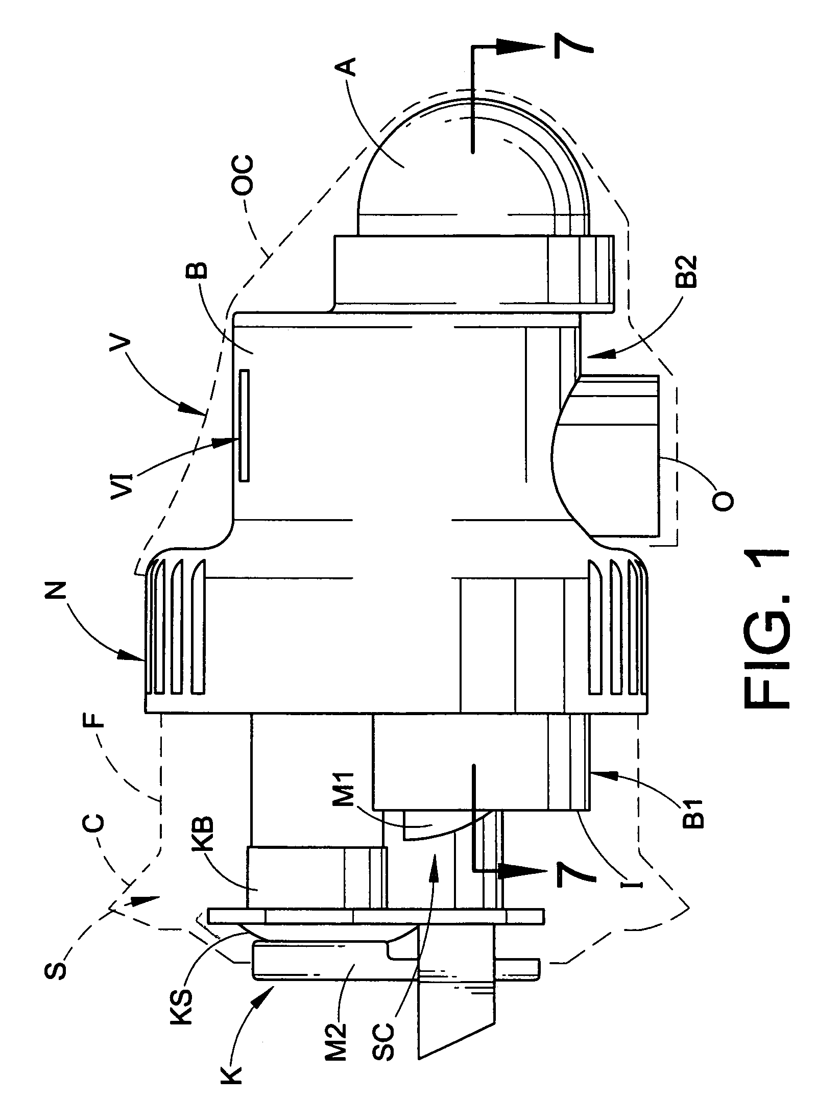
[0016]FIGS. 1-5 illustrate a valve V formed in accordance with the present invention operatively connected to a rigid, i.e., non-collapsible, container C for dispensing liquid L contained in an interior space S of the container. More particularly, the valve V comprises a body B including a first portion B1 that is mated with an outlet F of the container C in a fluid-tight relationship. As shown herein, the first body portion B1 is received within the container outlet F. An integral or separate nut N is threaded to the outlet F and fixedly secures the valve V to the container C. In the case of an integral nut N, as shown, the nut N is defined as a one-piece construction with the body B. In the case of a separate nut, the nut is captured on the body B by a flange, and the flange of the body is captured between the container C and the nut when the nut is threadably engaged to the container outlet F. Container C is unvented and does not collapse when emptied and, as such, the valve V mu...


PUM


Abstract

A valve includes a body; a liquid flow passage defined in the body and including a liquid inlet and a liquid outlet; a vent passage defined in the body and including an air inlet and an air outlet; a valve seat defined in the liquid flow passage; a liquid seal located adjacent the valve seat; a stem connected to the liquid seal and extending in the liquid flow passage away from the liquid seal through an aperture defined in the body. The stem includes a distal end located external to the body. The stem is movable to and from a first position where the liquid seal is mated with the valve seat and a second position where the liquid seal is unseated from the valve seat. An actuator is connected to the distal end of the stem. The actuator is selectively movable to move the stem from the first position to the second position. A check-valve is adapted to block flow of liquid from the air outlet to the air inlet in the vent passage, and to allow flow of air from the air inlet to the air outlet in said vent passage. The valve optionally further includes a surge control device and / or a keeper for the check-valve seal.

Description

CROSS-REFERENCE TO RELATED APPLICATIONS[0001]This application claims priority from and benefit of the filing date of U.S. provisional application No. 60 / 655,547 filed Feb. 23, 2005, U.S. provisional application No. 60 / 591,835 filed Jul. 28, 2004 and U.S. provisional application No. 60 / 555,453 filed Mar. 23, 2004, and the disclosures of each of these provisional applications is hereby expressly incorporated by reference herein.BACKGROUND[0002]Dispensing liquid from a non-vented rigid container (i.e., sufficiently rigid to resist collapsing when liquid is dispensed) requires that air be vented into the container through the valve to obtain proper flow. Use of a conventional, unvented valve for dispensing liquid will result in liquid flow, if any, that is uneven and insufficient in terms of flow-rate as air must enter the container through the liquid flow passage. Vented valves that allow air to flow into the container are known but have been found to be unsatisfactory for many applica...

Claims


Application Information

Patent Timeline
Patent Type & Authority Patents(United States)
IPC IPC(8): B67D3/00B65D25/40F16K24/00F16K31/12B67D3/04B67D7/24F16K24/02
CPCB67D3/044F16K24/02Y10T137/86332
Inventor LABINSKI, JEFFERY J.MEYER, MICHAEL H.
Owner FOODSERVICES BRAND GRP LLC (
Why Eureka
Try Eureka