Ball throwing device

a technology for throwing devices and balls, which is applied in the field of throwing devices, can solve the problems of tiring for the dog owner, never tireing the dog, and difficulty in throwing balls a long distan

Inactive Publication Date: 2009-04-21
ROSE AMERICA
View PDF26 Cites 22 Cited by
  • Summary
  • Abstract
  • Description
  • Claims
  • Application Information

AI Technical Summary

Problems solved by technology

However, the dog never seems to tire running after the ball and retrieving it which can be tiring for the dog owner.
Furthermore, throwing a ball a long distance can be difficult and throwing a ball a long distance repeatedly can be very tiring.
However, this takes some coordination.

Method used


Image

  • Ball throwing device
  • Ball throwing device
  • Ball throwing device

Examples


Embodiment Construction

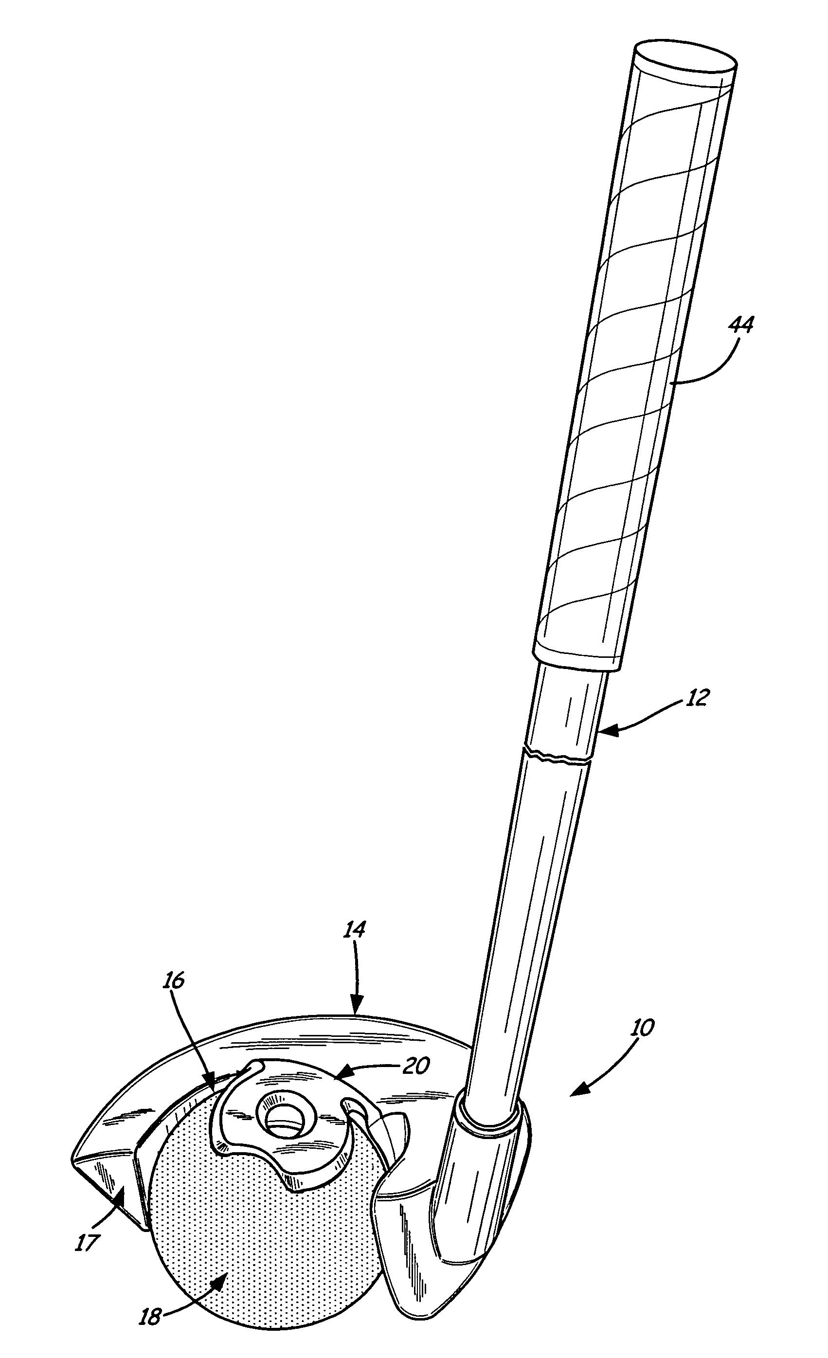
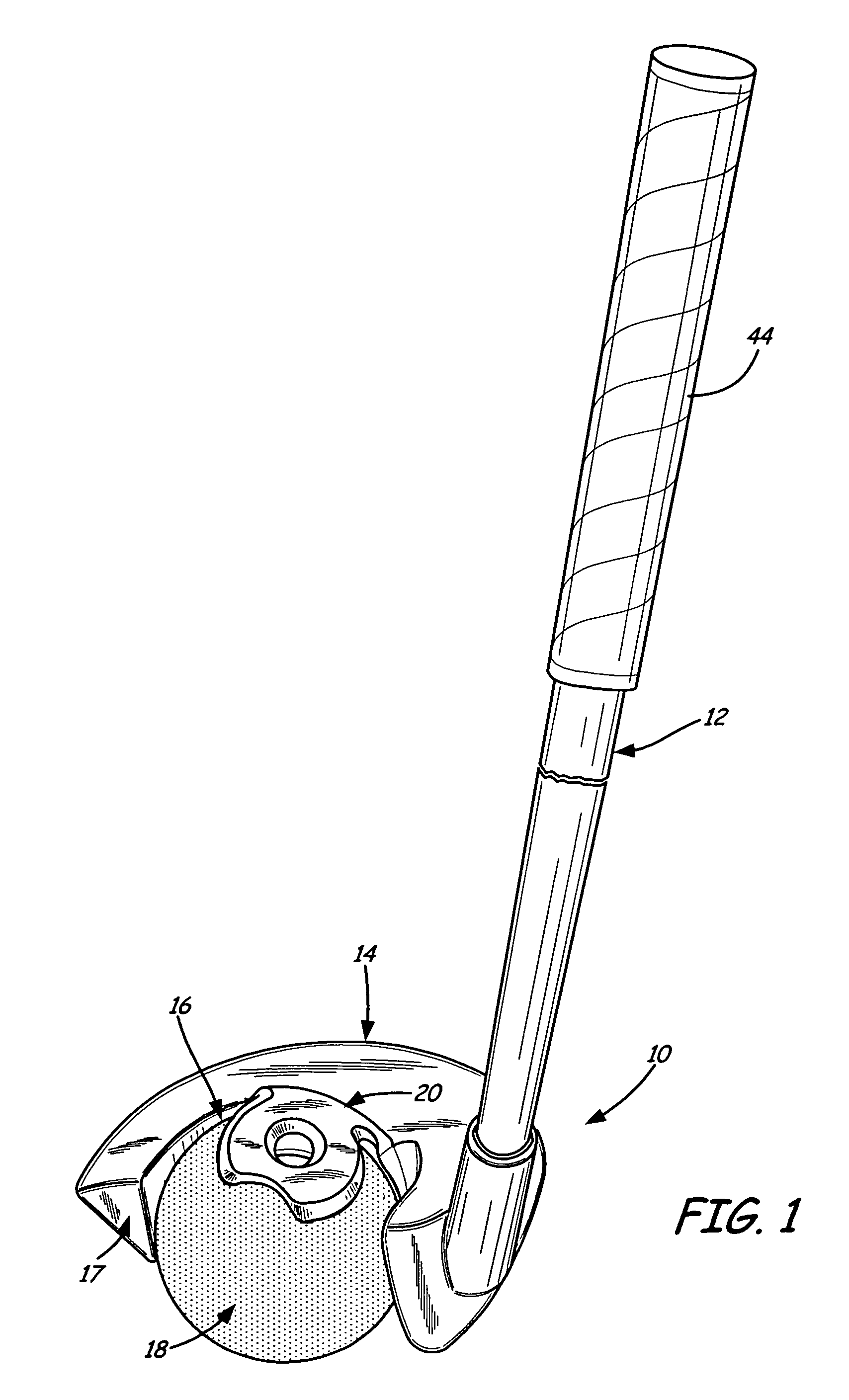
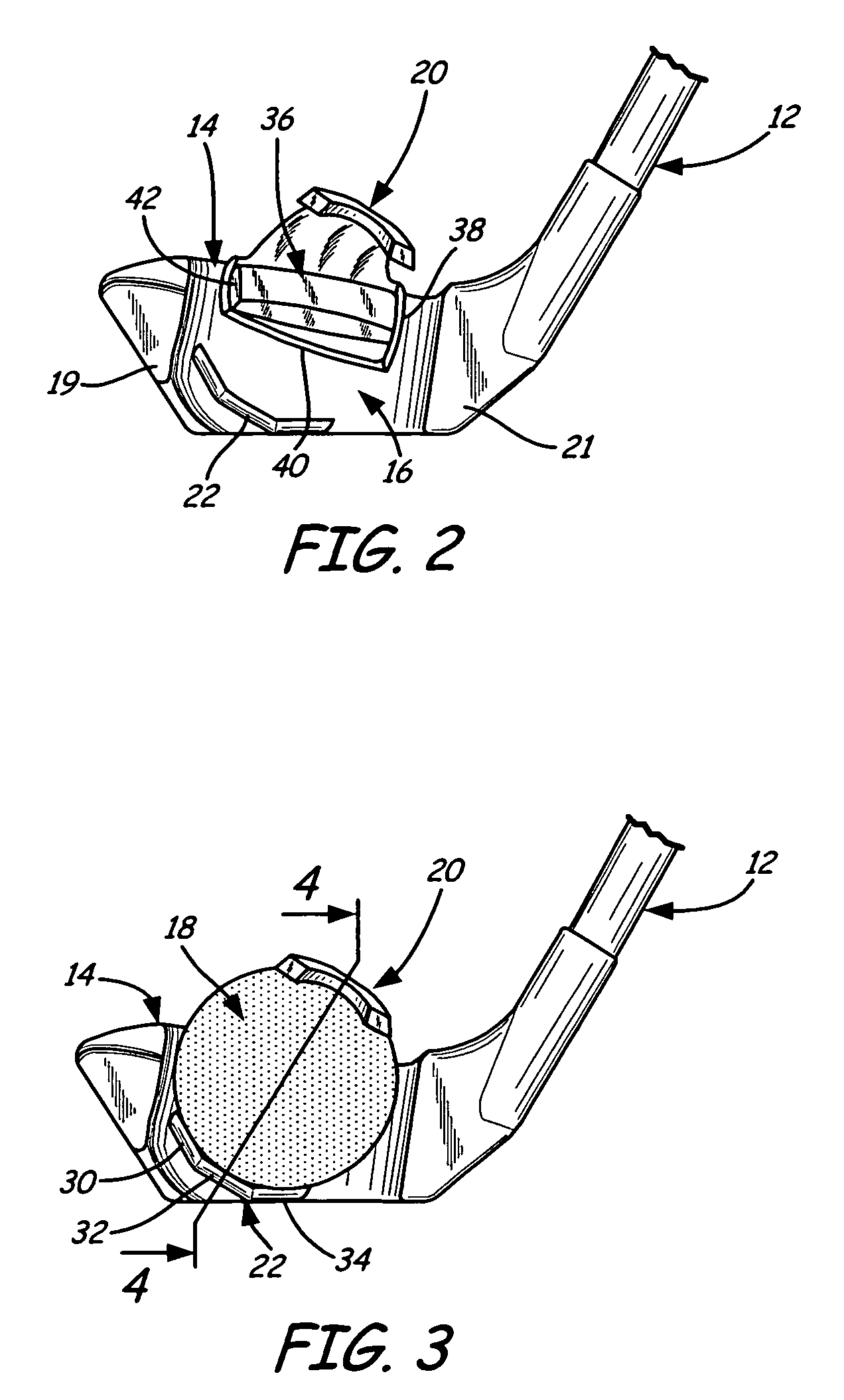
[0012]The present invention includes a ball launching device generally indicated at 10 in FIG. 1. The ball launching device 10 is designed to look and function much like a golf club. The device 10 includes a shaft 12 attached to a head 14. The head 14 includes a face portion 17 having a socket 16 sized to hold a ball 18. The socket 16 is generally positioned between a toe portion 19 of the club and a heel portion 21 of the club.

[0013]The club head 14 is preferably made of a plastic material and is integrally molded as one piece. The shaft 12 is similar to a golf club shaft and can be made of metal or graphite composite or any other material suitable for a golf shaft. Positioned on an upper portion of the shaft is a handle section 44 comprised of a grip that is the same or similar to a golf club grip.

[0014]The socket 16 as best illustrated in FIGS. 2-4, includes upper and lower retaining members 20 and 22. The upper and lower retaining members are spaced sufficiently apart to engage ...


PUM


Abstract

A ball launching device for launching a ball includes a shaft and a head attached to the shaft. The head includes a face having a socket for releasably retaining the ball such that when the head is swung, the ball is released.

Description

CROSS-REFERENCE TO RELATED APPLICATION[0001]The present application is based on and claims the benefit of U.S. provisional patent application Ser. No. 60 / 662,630, filed Mar. 16, 2005, the content of which is hereby incorporated by reference in its entirety.FIELD OF THE INVENTION[0002]The present invention relates to a device for throwing a ball, and in particular, it relates to a device with which a ball is held at the end of a shaft and is launched during a swing of the shaft.BACKGROUND OF THE INVENTION[0003]Throwing a ball to a dog so that the dog retrieves the ball for the dog owner is great exercise for the dog. However, the dog never seems to tire running after the ball and retrieving it which can be tiring for the dog owner. Also, it is desirable to throw the ball a long distance. Depending on the dog owner, this is often times not possible. Furthermore, throwing a ball a long distance can be difficult and throwing a ball a long distance repeatedly can be very tiring.[0004]Som...

Claims


Application Information

Patent Timeline
Patent Type & Authority Patents(United States)
IPC IPC(8): A63B53/00A63B59/00
CPCA63B59/02A63B53/00A63B59/0088A63B59/20A63B60/50
Inventor WINCHESTER, STEPHEN R.
Owner ROSE AMERICA
Why Eureka
Try Eureka