X-ray CT apparatus

a ct apparatus and x-ray technology, applied in the field of x-ray ct apparatus, can solve the problems of not being able to cover the whole heart with data acquisition per rotation, the method involves a problem in terms of x-ray exposure, and the problem of not being able to achieve the effect of covering the whole hear

Active Publication Date: 2009-04-21
GENERAL ELECTRIC CO
View PDF24 Cites 28 Cited by
  • Summary
  • Abstract
  • Description
  • Claims
  • Application Information

AI Technical Summary

Benefits of technology

[0007]Therefore, an object of the present invention is to provide an X-ray CT apparatus capable of realizing the photography or imaging of a heart at a low dosage and a high speed and with good image quality by a helical scan, variable pitch helical scan or helical shuttle scan of the X-ray CT apparatus having a multi-row X-ray detector or a two-dimensional X-ray area detector of matrix structure typified by a flat panel X-ray detector.

Problems solved by technology

The present imaging method involves a problem in terms of X-ray exposure because of the low helical pitch.
However, as in the case in which multi-segment image reconstruction is taken as shown in FIGS. 17 and 18 to adapt to various heartbeats, problems arise even in terms of image quality as in the case of the occurrence of artifacts due to displacements in X-ray projection data between respective segments, the occurrence of banding artifacts in the direction orthogonal to a z direction parallel to an xy plane at a three-dimensional display as shown in FIG. 20, and the like.
On the other hand, since a z direction X-ray detector width is not yet sufficient in the normal conventional scan (axial scan), data acquisition per rotation is not capable of covering the whole heart.

Method used


Image

  • X-ray CT apparatus
  • X-ray CT apparatus
  • X-ray CT apparatus

Examples


first embodiment

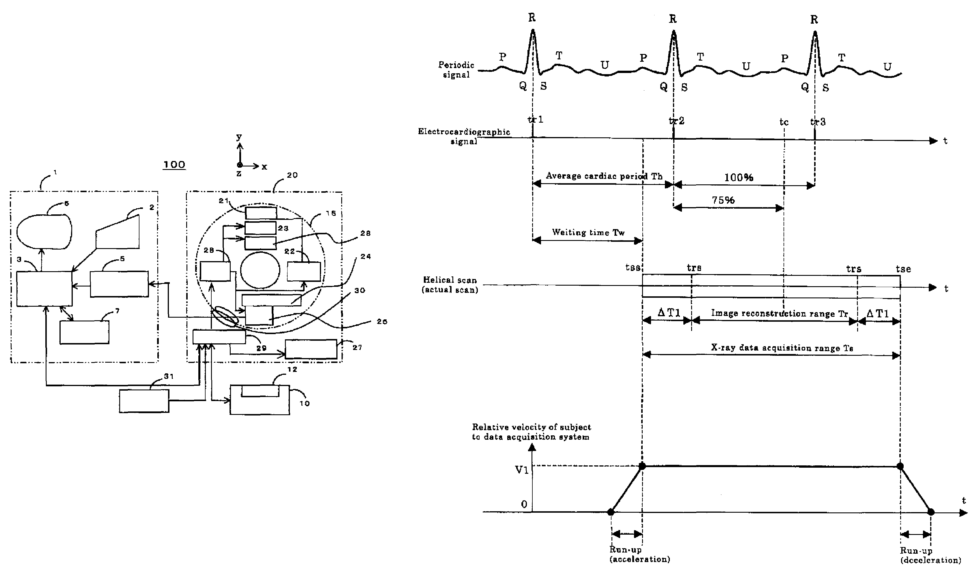
[0123]The first embodiment illustrates the embodiment wherein the appropriateness of the phase of the electrocardiographic signal is determined in advance by the high-speed helical scan large in helical pitch at low X-ray dosage and thereafter the helical scan for the actual scan is performed by means of test injection or contrast agent synchronous photography.

[0124]FIGS. 16, 17, 18 and 19 are respectively diagrams for describing the prior art and respectively show the image of the conventional heart imaging process. So-called electrocardiographic synchronous photography or imaging synchronized with the heartbeat has heretofore been performed upon photography of a cardiac coronary r or the like. As the electrocardiographic synchronous photography or imaging, there are known prospective imaging in which while the average of a plurality of immediately-preceding cardiac cycles or periods is being observed, projection data are acquired in sync with, for example, 75% phase of the average...

second embodiment

[0166]A second embodiment shows an embodiment of a method illustrative of the contrast agent synchronous imaging employed in Step S15 or Step S17 shown in FIG. 23 of the first embodiment

[0167]FIG. 28 shows an example of the flow of processing for the contrast agent synchronous imaging.

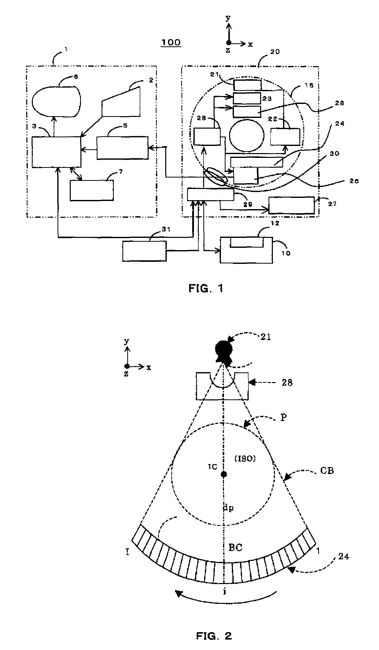
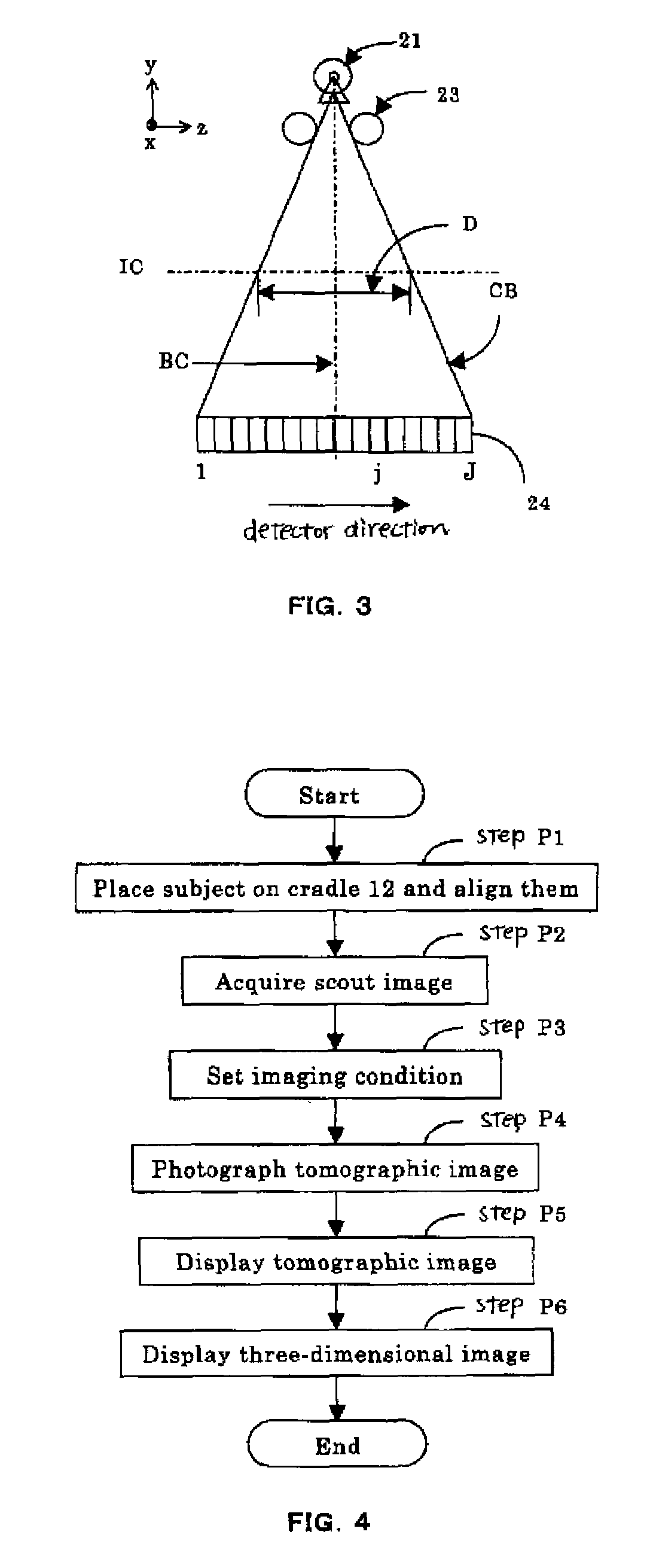
[0168]At Step C1, a subject is placed on the cradle 12 and they are aligned with each other.

[0169]At Step C2, scout image acquisition is performed.

[0170]At Step C3, an imaging condition setting is carried out.

[0171]At Step C4, baseline tomographic image imaging is performed.

[0172]At Step C5, a baseline tomographic image display is done.

[0173]At Step C6, a contrast agent synchronous imaging condition setting is carried out. A region-of-interest setting on a baseline tomographic image is carried out.

[0174]At Step C7, a monitor scan is started. The monitor scan is shown in FIG. 29.

[0175]At Step C8, it is decided whether an average CT value in the region of interest exceeds a set threshold value. If the an...


PUM

PropertyMeasurementUnit
widthaaaaaaaaaa
lengthaaaaaaaaaa
view angleaaaaaaaaaa

Abstract

An X-ray CT apparatus includes an X-ray data acquisition device for acquiring X-ray projection data transmitted through a subject lying between an X-ray generator and an X-ray detector having a two-dimensional detection plane and detecting X rays in opposition to the X-ray generator, while the X-ray generator and the X-ray detector are being rotated about a center of rotation lying there between; an image reconstructing device for image-reconstructing the acquired projection data; an image display device for displaying the image-reconstructed tomographic image; and an imaging condition setting device for setting various kinds of imaging conditions for tomographic image, wherein the X-ray data acquisition device acquires X-ray projection data in sync with an external sync signal by a helical scan with a predetermined range of the subject with a helical pitch set to 1 or more.

Description

CROSS REFERENCE TO RELATED APPLICATIONS[0001]This application claims the benefit of Japanese patent application number 2006-105749 filed Apr. 6, 2006.BACKGROUND OF THE INVENTION[0002]The present invention relates to an X-ray CT apparatus or a technique for an X-ray CT image photographing or imaging method, which realize cardiac imaging or biological synchronous imaging based on low radiation exposure, high image quality and high-speed photography by an electrocardiographically-synchronized helical scan, variable-pitch helical scan or helical shuttle scan at a medical X-ray CT (Computed Tomography) apparatus.[0003]In an X-ray CT apparatus using a multi-row X-ray detector or an X-ray CT apparatus using a two-dimensional X-ray area detector of a matrix structure typified by a flat panel, the photography of the heart has heretofore been performed by a helical scan electrocardiographically synchronized at a helical pitch made slow by a helical pitch 0.2 or so as shown in FIG. 16. As the ...

Claims


Application Information

Patent Timeline
Patent Type & Authority Patents(United States)
IPC IPC(8): G01N23/083H05G1/62
CPCA61B6/032A61B6/481A61B6/504A61B6/541G01N23/046A61B6/027A61B5/0452A61B5/7207A61B6/503G01N2223/419A61B5/349A61B6/03
Inventor IMAI, YASUHIRO
Owner GENERAL ELECTRIC CO
Why Eureka
Try Eureka