Pry bar ergonomic handle

a technology of ergonomic handle and pry bar, which is applied in the field of pry bar ergonomic handle, can solve the problems of cumbersome gripping and use of pry bars of all metal construction

Inactive Publication Date: 2009-04-28
MAYHEW STEEL PRODS
View PDF45 Cites 34 Cited by
  • Summary
  • Abstract
  • Description
  • Claims
  • Application Information

AI Technical Summary

Benefits of technology

[0013]A pry bar ergonomic handle has a longitudinal axis and a grip portion having an upper convex surface and a lower concave surface with a recess formed in the distal end of the upper surface to receive the thumb, and the grip portion further includes oppositely disposed bulged sides. The user's grip hand engages the upper and lower surfaces with the palm engaging one of the bulged side

Problems solved by technology

In general, pry bars were of all metal const

Method used


Image

  • Pry bar ergonomic handle
  • Pry bar ergonomic handle
  • Pry bar ergonomic handle

Examples


Embodiment Construction

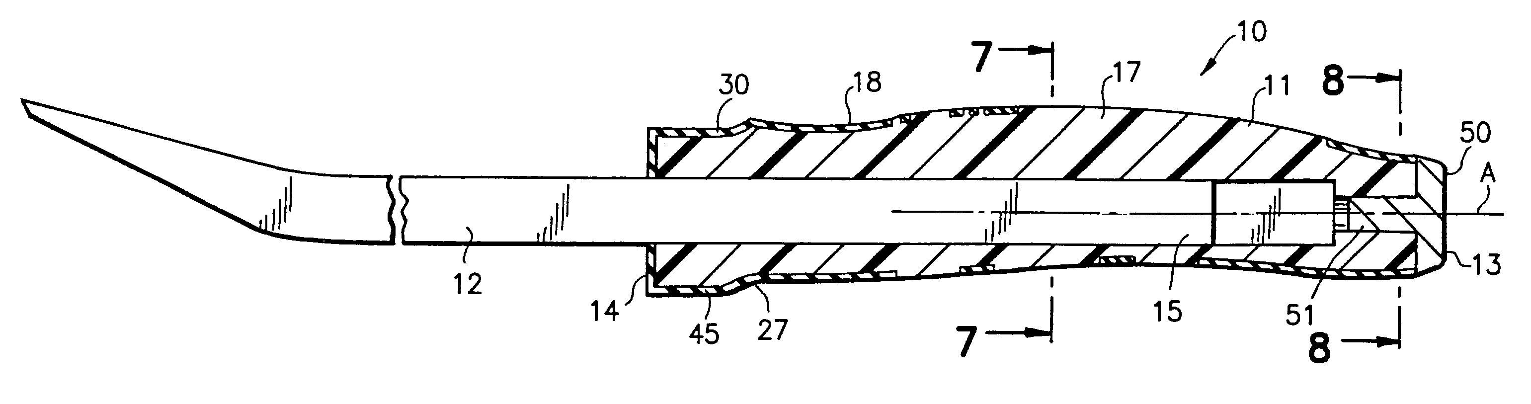
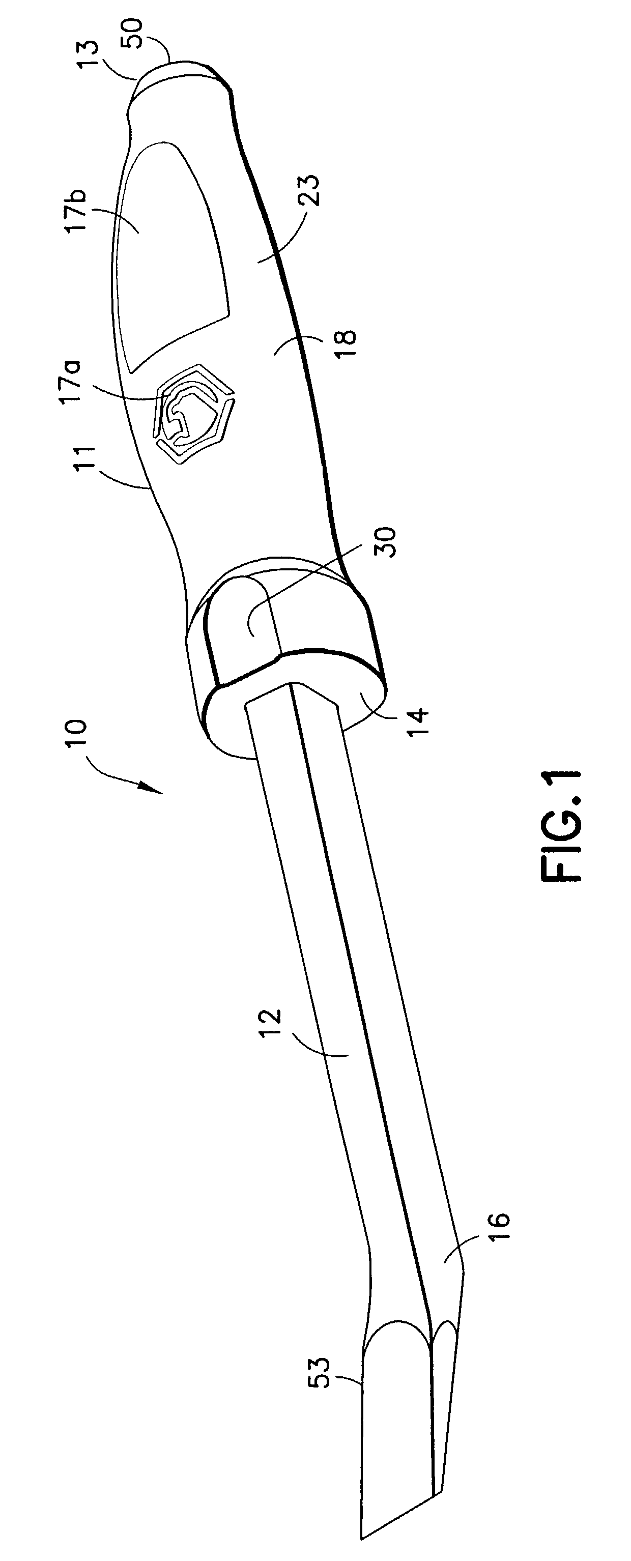
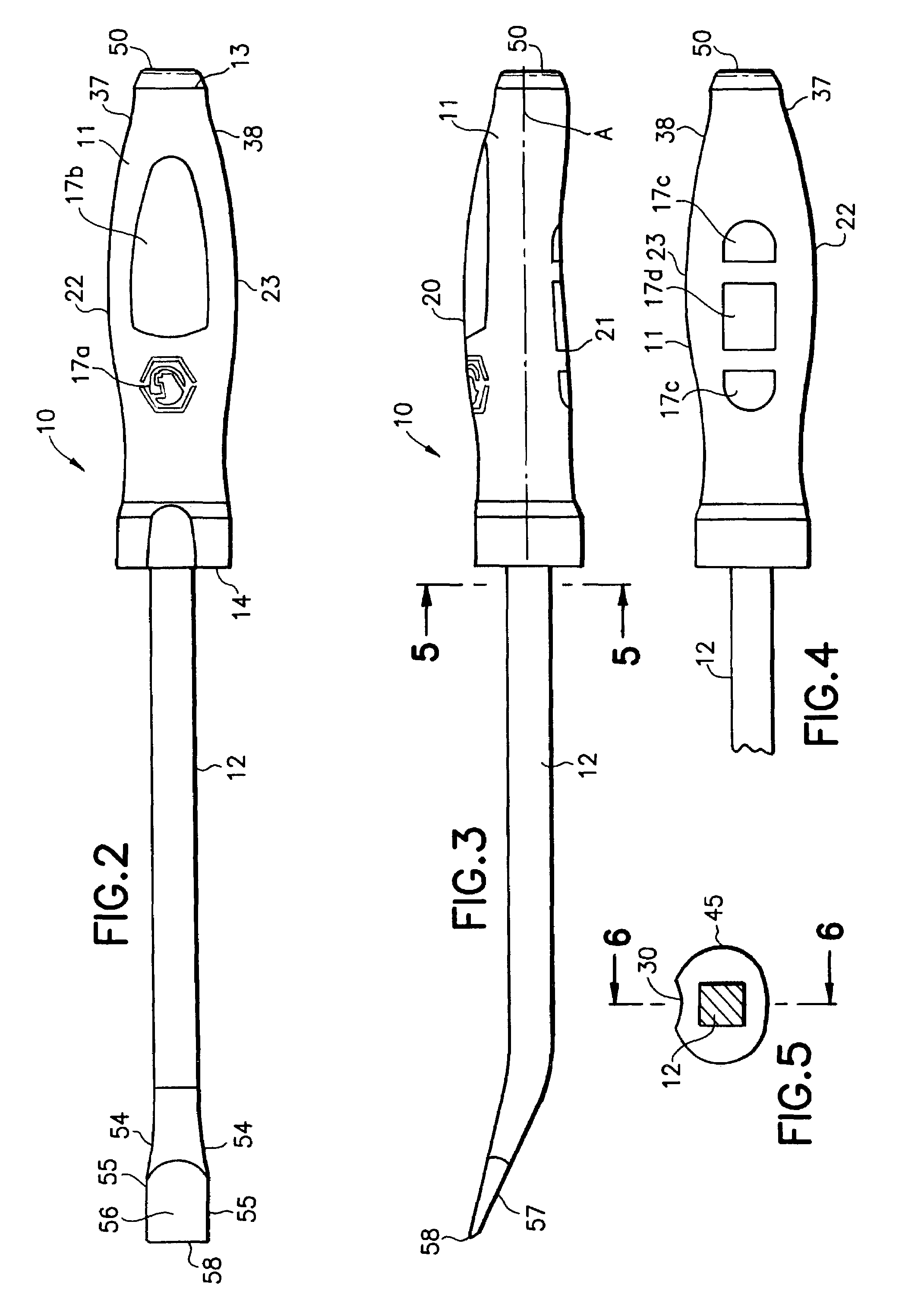
[0022]Referring to FIGS. 1-8, there is shown pry bar 10 of the present invention. Pry bar 10, in general terms, includes handle 11 and a fixedly attached metal shank or blade 12. Handle 11 has a proximate end 13 and a distal end 14. Shank 12 has a proximate end 15 and a distal end 16. Handle 11 is formed of a hard thermoplastic molded core 17 and a molded over integrally bonded elastomeric cover 18, wherein cover 18 is formed of relatively soft elastomeric material.

[0023]The proximate end 25 of blade 12 is securely fixedly molded in core 17, with the formation of core 17, by means known in the art. The elastomeric cover 18 is then molded over or around the core by means well known in the knife, screwdriver, and like bladed hand tool handle prior art.

[0024]Handle 11 grip portion has an upper grip surface 20 and oppositely disposed lower grip surface 21, and oppositely disposed bulged sides 22 and 23. Handle 11 has an elongated central axis A, as best shown in FIGS. 3 and 6. Upper gri...


PUM


Abstract

A pry bar has an ergonomic handle formed with a grip portion having convex upper grip surface and a concave lower grip with an inner hard thermoplastic core and an outer elastomeric molded over cover. The convex upper grip surface portion is more distantly disposed from the handle longitudinal axis than the curved lower grip surface portion. The upper grip surface is formed with a distally disposed outwardly flared guard formed with thumb receiving recess. The handle sides are formed with elongated outwardly bulged contoured respective palm engaging portions for right or left handed grip engagement.

Description

RELATED PRIOR APPLICATIONS[0001]This application is a continuation-in-part application of Ser. No. 10 / 420,432, filed Apr. 22, 2003, now U.S. Pat. No. 6,772,994.BACKGROUND OF THE INVENTION[0002]This invention relates to pry bars and pry bar handles. Specifically, this invention relates to a pry bar ergonomic handle.BACKGROUND AND DISCUSSION OF THE PRIOR ART[0003]In general, pry bars were of all metal construction and were cumbersome to grip and use. Often the user has to grip a rectilinear metal portion of the pry bar in use. One such prior art construction is disclosed in U.S. Pat. No. 6,058,809 to Flanz.[0004]A wrecking tool is disclosed in U.S. Patent application Publication No. 2002 / 0134971 to Christensen. The Christensen tool has an elongate octagonal cross-sectional metal handle or bar stock portion. A non-octagonal handgrip is attached to the octagonal metal bar.[0005]It was generally known to provide a soft elastomeric molded over cover on a molded hard thermoplastic core for...

Claims


Application Information

Patent Timeline
IPC IPC(8): E05B1/00B25C11/00B25G1/10
CPCB25B33/00B25G1/105B25G1/102Y10T16/476
Inventor LAWLESS, JOHN C.
Owner MAYHEW STEEL PRODS
Why Eureka
Try Eureka