Nonlinear polarization pulse shaping model locked fiber laser at one micron with photonic crystal (PC), photonic bandgap (PBG), or higher order mode (HOM) fiber

a fiber laser and polarization technology, applied in the direction of electrical equipment, basic electric elements, laser details, etc., can solve the problems of affecting the distortion of pulse shapes, and the inability to achieve the practical application of ultra-short pulse and high power lasers

Active Publication Date: 2009-05-05
POLARONYX
View PDF4 Cites 7 Cited by
  • Summary
  • Abstract
  • Description
  • Claims
  • Application Information

AI Technical Summary

Benefits of technology

[0011]It is therefore an aspect of the present invention to provide a method of using nonlinear polarization evolution (NPE) and dispersion managed fiber cavity to manipulate the pulse propagation in the cavity and balance the self phase modulation (SPM) and dispersion induced pulse broadening / compressing. This method of polarization pulse shaping generates transform-limited pulse shapes through combinational effects of fiber length, the non-linear effects and dispersion such that the above-described difficulties encountered in the prior art can be resolved.

Problems solved by technology

Conventional technologies of generating short pulse mode-locked fiber laser are still confronted with technical difficulties and limitations that the practical applications of the ultra-short pulse and high power laser cannot be easily achieved.
Specifically, the practical usefulness of the ultra-short high power lasers are often hindered by the pulse shapes distortions.
Furthermore, such laser systems are often bulky, difficult for alignment maintenance, and also lack sufficient robustness.
All these difficulties prevent practical applications of the ultra-short high power lasers.
Historically, generation of mode-locked laser with the pulse width down to a femtosecond level is a difficult task due to limited resources of saturation absorbers and anomalous dispersions of fibers.
Conventionally, short pulse mode locked fiber lasers operated at wavelengths below 1.3 μm present a particular challenge is that there is no simple all fiber based solution for dispersion compensation in this wavelength regime.
Unfortunately these devices require the coupling of the fiber into a bulk device, which results in a laser that is highly sensitive to alignment and thus the environment
However, such configurations often developed into bulky and less robust systems due to the implementations of free space optics.
The limitations for practical application of such laser systems are even more pronounced due the pulse shape distortions when the pulse width is further reduced compounded with the requirement of high power fiber amplification.
When the pulse width narrows down to femtosecond level and the peak power increases to over 10 kW, strong nonlinear effects such as self phase modulation (SPM) and XPM will cause more serious spectral and temporal broadening.
These nonlinear effects and spectral and temporal broadening further causes a greater degree of distortions to the laser pulses.
The technical difficulties cannot be easily resolved even though a large mode area (LMA) fiber can be used to reduce SBS and SRS to increase saturation power.
However, the large mode area fiber when implemented will in turn cause a suppression of the peak power and leads to an undesirable results due to the reduction of the efficiency
For these reasons, the conventional technologies do not provide an effective system configuration and method to provide effective ultra-short pulse high power laser systems for generating high power laser pulses with acceptable pulse shapes.
In addition to the above described difficulties, these laser systems require grating pairs for dispersion control in the laser cavity.
Maintenance of alignment in such systems becomes a time consuming task thus prohibiting a system implemented with free space optics and grating pairs from practical applications.
Also, the grating pairs further add to the size and weight of the laser devices and hinder the effort to miniaturize the devices implemented with such laser sources.

Method used


Image

  • Nonlinear polarization pulse shaping model locked fiber laser at one micron with photonic crystal (PC), photonic bandgap (PBG), or higher order mode (HOM) fiber
  • Nonlinear polarization pulse shaping model locked fiber laser at one micron with photonic crystal (PC), photonic bandgap (PBG), or higher order mode (HOM) fiber
  • Nonlinear polarization pulse shaping model locked fiber laser at one micron with photonic crystal (PC), photonic bandgap (PBG), or higher order mode (HOM) fiber

Examples


Embodiment Construction

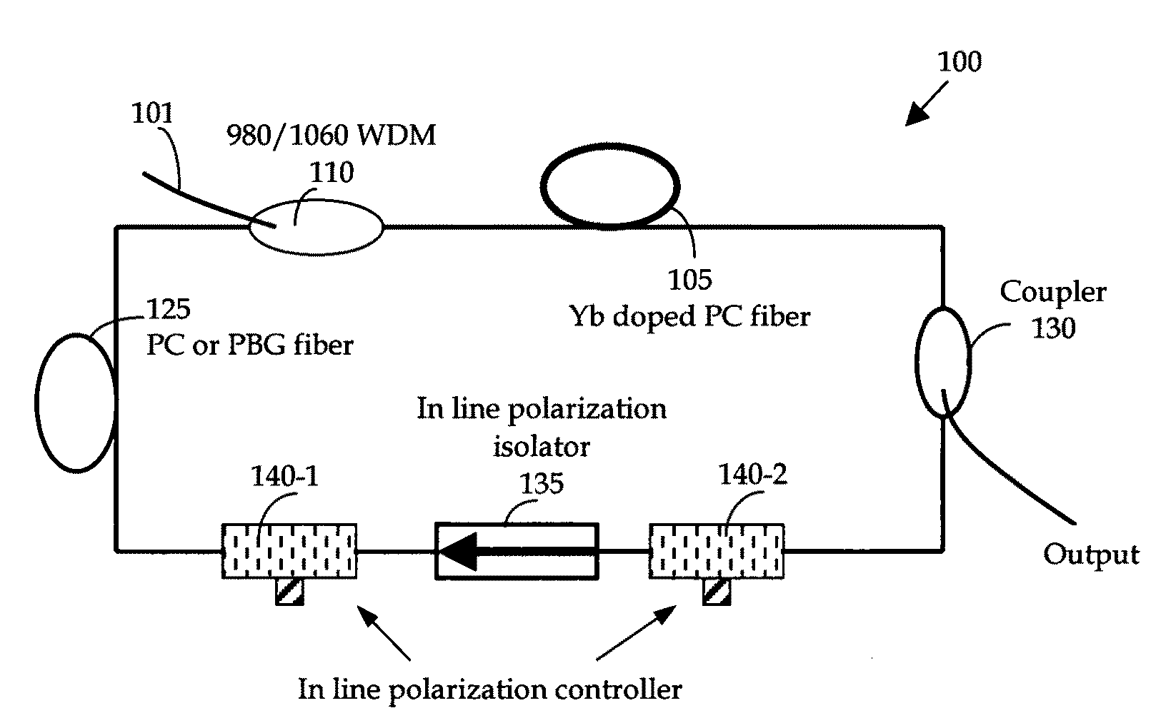
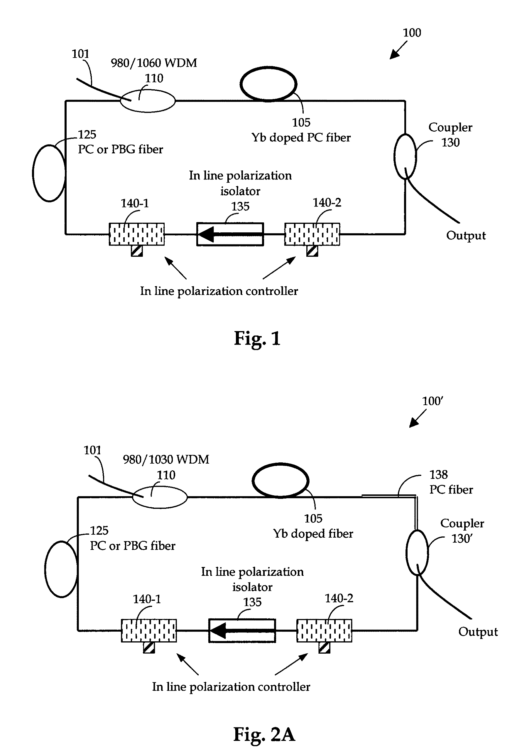
[0024]FIG. 1 is a schematic diagram of an ultra compact and low cost all-fiber based high power femtosecond fiber laser system of this invention. This is a laser system formed with all fiber-based components. The fiber laser has a ring configuration receiving a laser input through wavelength de-multiplexing (WDM) device 110 of a source laser that may have ranges of wavelengths, e.g., 980 or 1550 nm. The all fiber-based laser 100 is implemented with a Yb doped fiber 105 as a gain medium to amplify and compress / stretch the pulse. The Yb gain fiber can be either PC fiber or regular single mode Yb doped fiber. A telecom grade 980 nm pump laser is used to pump Yb ions for amplification of the intra cavity pulses. To compensate the dispersion and dispersion slope in the fiber laser cavity, instead of using grating pairs or prisms, another photonic crystal fiber or PBG fiber 125 is employed. Because PC or PBG fibers 125 can provide both normal and anomalous dispersion at 1060 nm range with...


PUM


Abstract

A fiber laser cavity that includes a laser gain medium for receiving an optical input projection from a laser pump, wherein the laser cavity further includes a normal dispersion fiber segment with a β″>0 where β″ representing a fiber dispersion, and an anomalous dispersion fiber segment with the β″<0 for generating a net anomalous dispersion for balancing a self-phase modulation (SPM) and a dispersion induced pulse broadening / compression in the fiber laser cavity for generating an output laser with a transform-limited pulse shape wherein the segment with the anomalous dispersion further includes a Photonic Crystal (PC), a Photonic Bandgap (PBG) or a higher order mode (HOM) fiber.

Description

[0001]This Formal Application claims a Priority Date of Mar. 31, 2006 benefited from a Provisional Application 60 / 788,226 filed by the same Applicant of this invention. This Formal Application is further a Continuation-in-part (CIP) of another patent application Ser. No. 11 / 136,040 filed on May 23, 2005 now abandoned by the same Applicant of this Patent Application. The disclosures made in the application Ser. No. 11 / 136,040 are hereby incorporated herein by reference.FIELD OF THE INVENTION[0002]The present invention relates generally to apparatuses and methods for providing short-pulsed mode-locked fiber laser. More particularly, this invention relates to new configurations and methods including the implementation of photonic crystal (PC) fiber, Photonic Band Gap (PBG) fiber, or a higher-order mode (HOM) fiber, for providing a nonlinear polarization pulse-shaping mode-locked fiber laser with improved and better controllable pulse shapes.BACKGROUND OF THE INVENTION[0003]Conventional...

Claims


Application Information

Patent Timeline
Patent Type & Authority Patents(United States)
IPC IPC(8): H01S3/30H01S3/10
CPCH01S3/06791H01S3/1112H01S3/06712H01S3/06741H01S3/1121H01S3/1618H01S2301/085
Inventor LIU, JIAN
Owner POLARONYX
Why Eureka
Try Eureka