Rotatable and pivotable connector

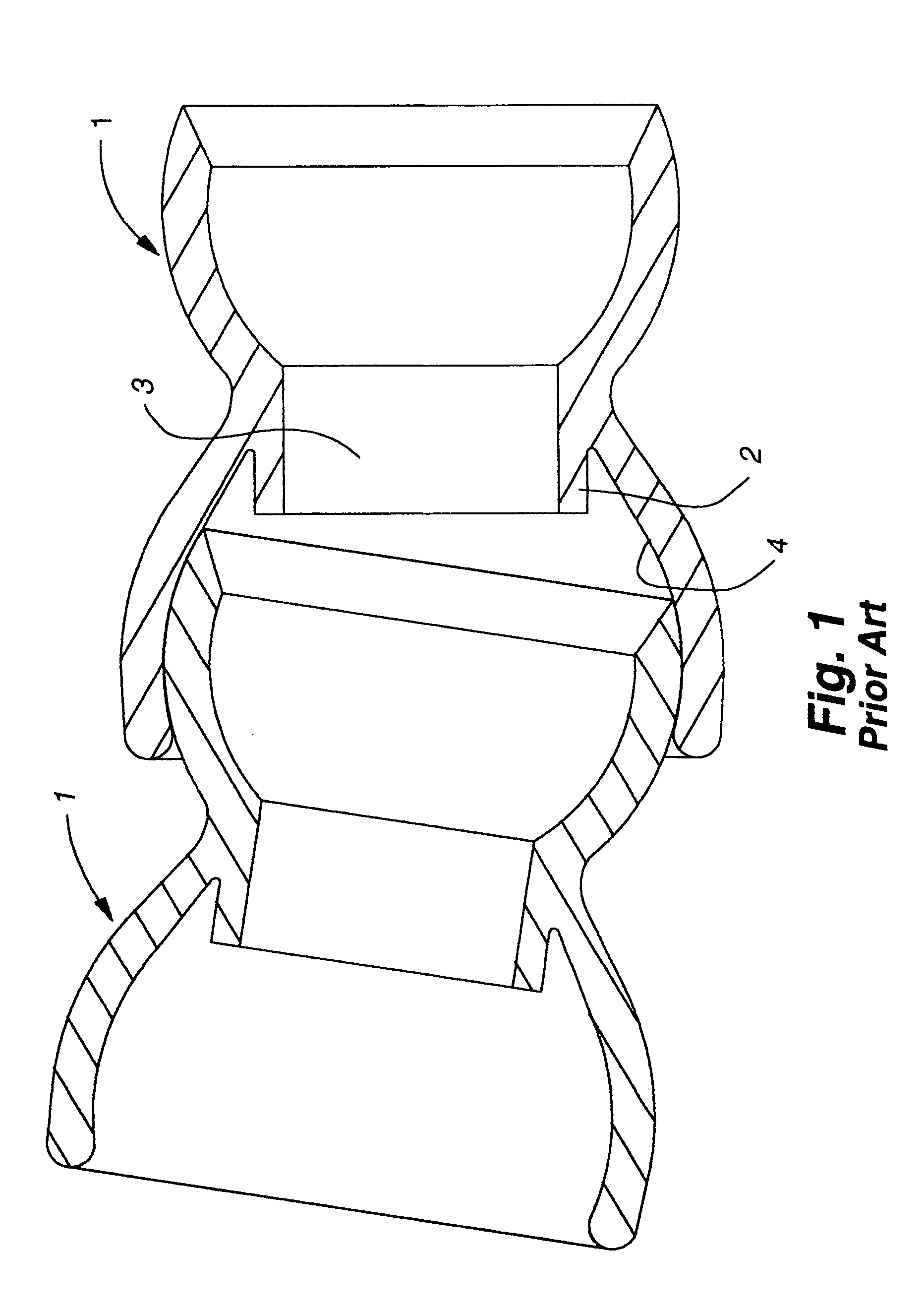
a technology of pivoting connectors and pivoting parts, which is applied in the direction of bending, siphoning, mechanical equipment, etc., can solve the problems of reducing the friction generated between adjacent connectors, loosening of connectors, and relatively complex structure of connectors b>1/b>

Active Publication Date: 2009-05-19
WATER PIK INC
View PDF823 Cites 1205 Cited by
  • Summary
  • Abstract
  • Description
  • Claims
  • Application Information

AI Technical Summary

Benefits of technology

[0012]The exterior retention element, such as, for example, a fitting, may restrict or limit the expansion of the female end of the connector. Such limitation may help prevent the female end of the connector from becoming disengaged from a male end of an adjacent connector. Alternately, the exterior retention element may help retain a fitting on the exterior of the female end of a connector.
[0013]In some embodiments, the connector may have a hollow neck, thus allowing the connector to define a passage within the connector from the male end to the female end.

Problems solved by technology

Generally, many of these connectors suffer from the same problem: under sufficient force, the ball of a first connector disconnects from the socket of an adjacent connector.
These connectors 1, however, are relatively structurally complex, requiring an inner annular ring 2 projecting into a passageway 3 defined through the middle of the connector 1.
With time, the connectors may loosen, and the friction generated between adjacent connectors may diminish.
In turn, this may cause the arm to bend undesirably under stresses it once may have been able to withstand.
Over time, creep may cause interconnected ball-and-socket connectors to deform.
Similarly, a ball nestled within the socket may continue to apply a load force to the socket, which eventually results in the ball disengaging from the socket.
Among other disadvantages, creep and resulting distortion may minimize the load capability, stationary holding force, and bending radius of a flexible arm.

Method used


Image

  • Rotatable and pivotable connector
  • Rotatable and pivotable connector
  • Rotatable and pivotable connector

Examples


Embodiment Construction

[0042]1. Overview and Structure of the Connector Body

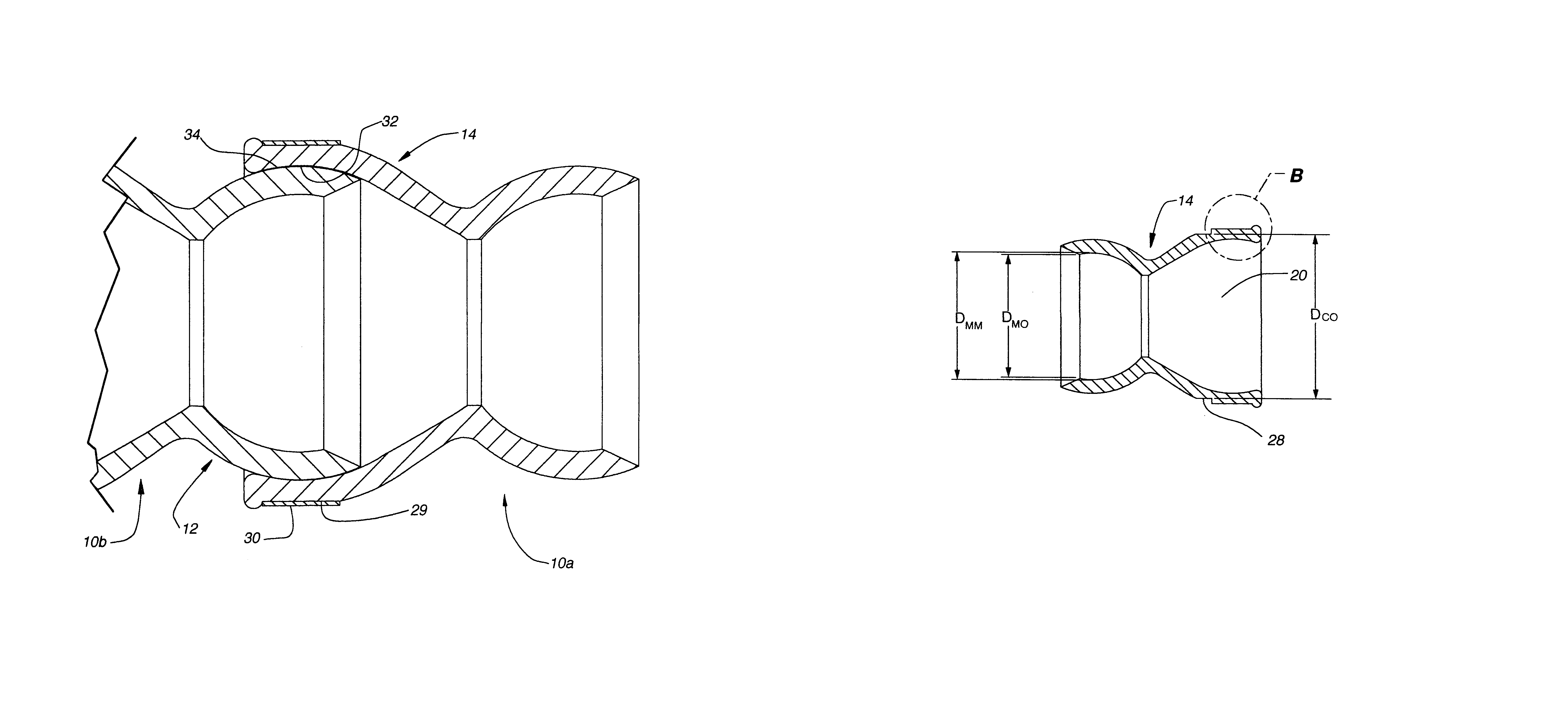
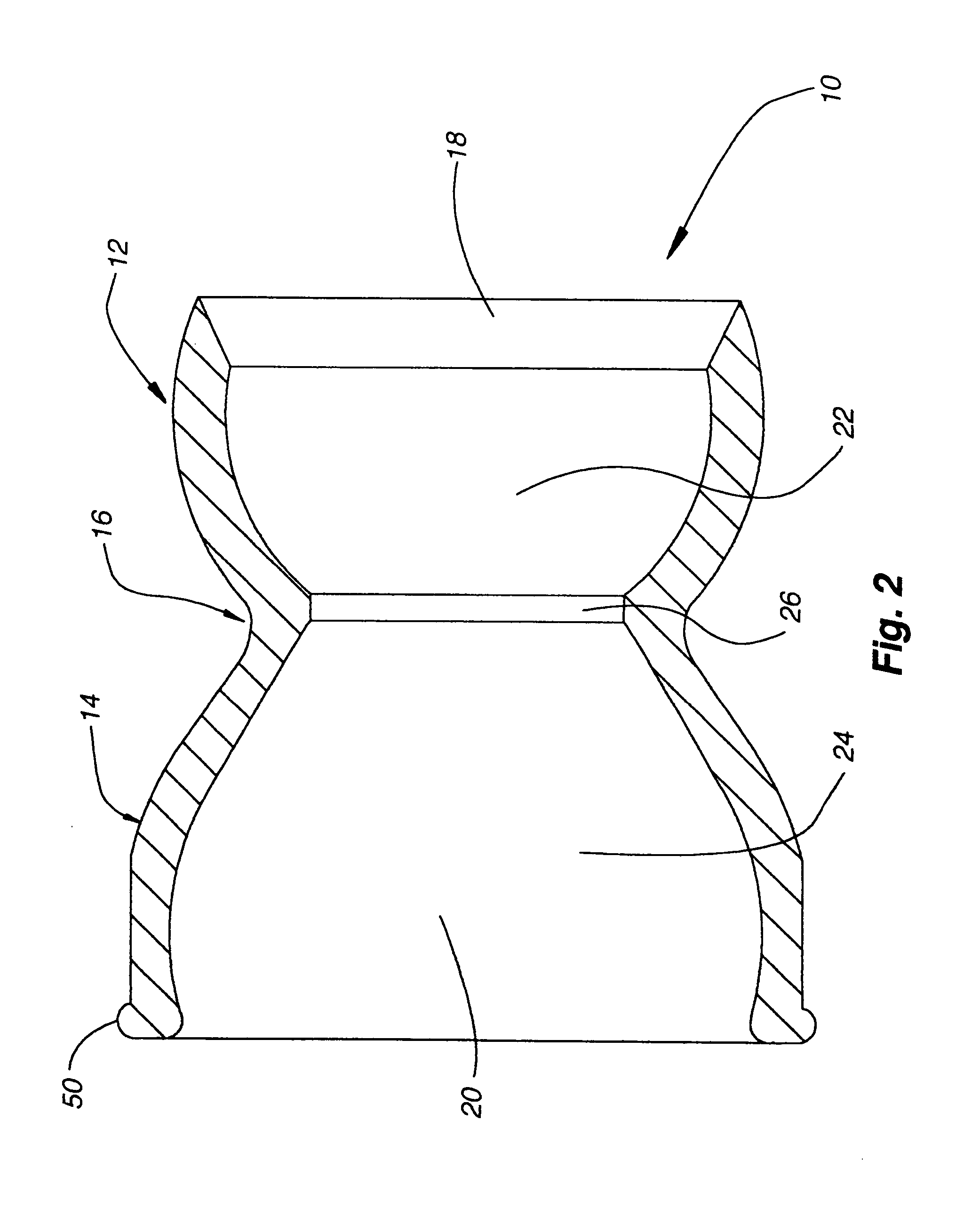
[0043]Generally, one embodiment of the present invention takes the form of a hollow connector. The connector, depicted in cross-section in FIG. 2, includes a connector body 10 (or colloquially, “bead”) having a male end 12 and a female end 14, as well as an optional external fitting (not shown in FIG. 2). The male end 12 of the connector may be referred to as a “ball,” and the female end 14 as a “socket.” Both the ball 12 and socket 14 are typically externally convex. The joinder between the male and female ends defines a narrowed portion or neck 16 of the bead 10, with both the ball 12 and socket 14 generally narrowing in lateral cross-section approaching the neck 16. For reference and as used herein, the longitudinal axis of the connector extends from the ball to the socket or vice versa, while the lateral axis of the connector is perpendicular to the longitudinal axis.

[0044]The connector body 10 is generally hollow throughout i...


PUM


Abstract

A rotatable, pivotable connector having a female end, a male end, a neck joining the male and female ends, and an exterior retention element. The exterior retention element, such as, for example, a fitting, may limit expansion of the exterior of the female end. The exterior retention element may also take the form of a retainer or similar structure to retain a fitting about the exterior of the female end of the connector. Further, the connector may be hollow, thus defining a continuous passage within. Also, multiple connectors may be interconnected to form an arm.

Description

RELATED APPLICATIONS[0001]This application claims the benefit of U.S. Provisional Application No. 60 / 511,253, entitled “Rotatable and Pivotable Connector” and filed Oct. 14, 2003, which is incorporated herein by reference in its entirety. This application also relates to U.S. Pat. No. 5,865,378, entitled “Flexible Shower Arm Assembly” and issued on Feb. 2, 1999, which is incorporated herein by reference in its entirety.BACKGROUND OF THE INVENTION[0002]1. Technical Field[0003]The invention relates generally to a rotatable connection structure, and more specifically to a rotatable and pivotable connector having an interior passageway permitting communication of fluids, solids, and gases therealong and an exterior fitting resisting disconnection of adjacent connectors.[0004]2. Background Art[0005]Many ball-and-socket connectors are presently in use. Generally, many of these connectors suffer from the same problem: under sufficient force, the ball of a first connector disconnects from t...

Claims


Application Information

Patent Timeline
Patent Type & Authority Patents(United States)
IPC IPC(8): F16L27/04F16BH01R35/00H01R39/00
CPCH01R35/00
Inventor LUETTGEN, HAROLD A.GOLICHOWSKI, GARY
Owner WATER PIK INC
Why Eureka
Try Eureka