Supercharge Your Innovation With Domain-Expert AI Agents!

Locking mechanism

a technology for locking mechanisms and mobile telephones, which is applied in the direction of cell components, casings/cabinets/drawers details, cell component details, etc., and can solve problems such as unsecure locking arrangements

Inactive Publication Date: 2009-05-26
LG ELECTRONICS INC
View PDF19 Cites 14 Cited by
  • Summary
  • Abstract
  • Description
  • Claims
  • Application Information

AI Technical Summary

Benefits of technology

The present invention is a locking mechanism that includes a spring-loaded locking member, a lock release device, and a latching member. The latching member is securely gripped by the spring-loaded locking member when the lock release device is only partially in contact with the spring-loaded locking member. The latching member is released from the grip of the spring-loaded locking member when the lock release device is forced in frictional sliding contact with the spring-loaded locking member against the spring bias of the spring-loaded locking member. This mechanism ensures safe and secure locking and unlocking of the device.

Problems solved by technology

This type of locking arrangement is not secure as an external impact such as from dropping the mobile telephone on the ground or the like may result in spring 18 being accidentally compressed enough to allow the release of lock portion 17 from latching portion 12a of battery cover 12.

Method used


Image

  • Locking mechanism
  • Locking mechanism
  • Locking mechanism

Examples


Embodiment Construction

[0021]Some embodiments of the present invention will be described in detail with reference to the related drawings of FIGS. 1-8. Additional embodiments, features and / or advantages of the invention will become apparent from the ensuing description or may be learned by practicing the invention.

[0022]In the figures, the drawings are not to scale with like numerals referring to like features throughout both the drawings and the description.

[0023]The following description includes the best mode presently contemplated for carrying out the invention. This description is not to be taken in a limiting sense, but is made merely for the purpose of describing the general principles of the invention.

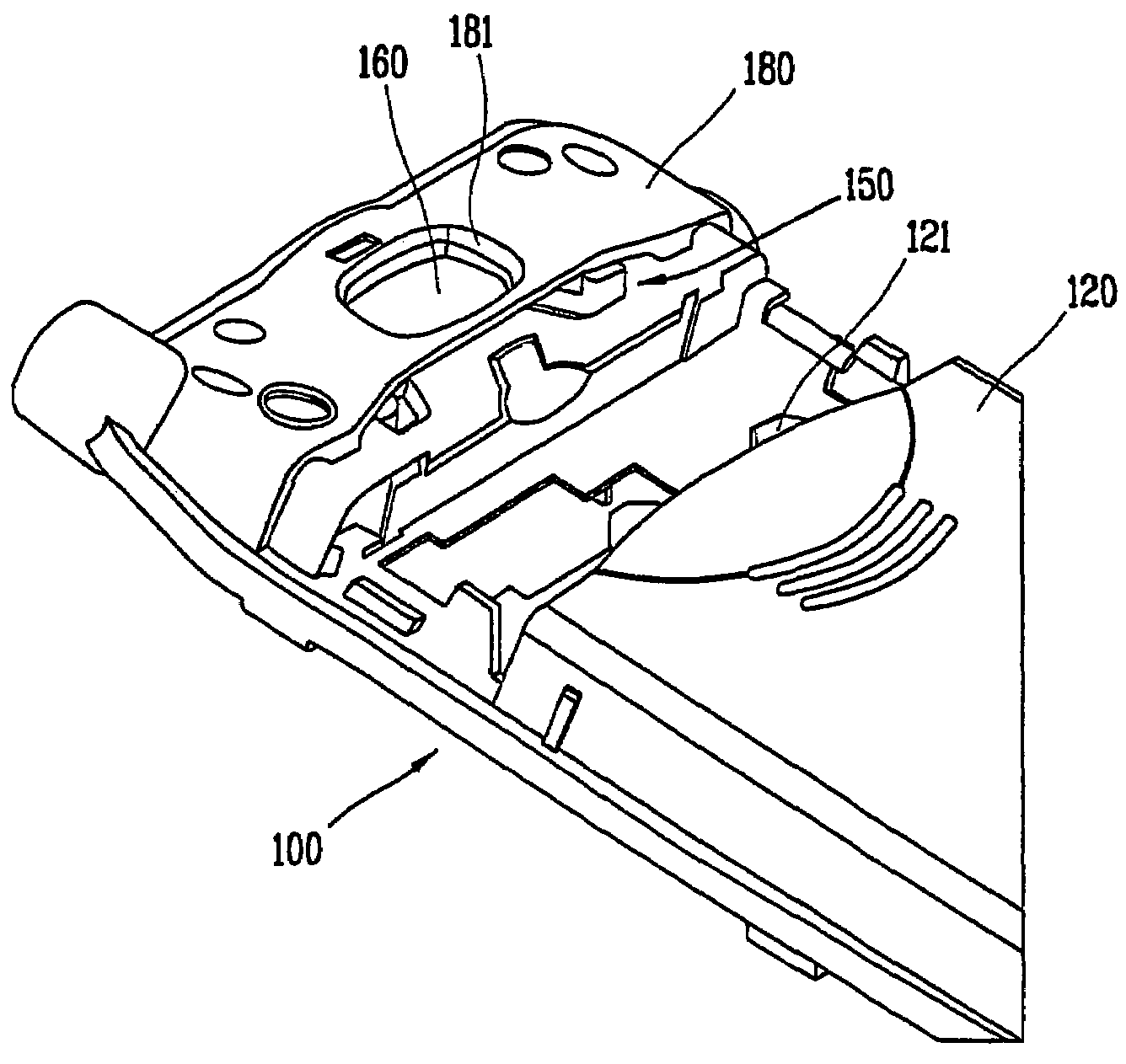
[0024]FIG. 4 schematically illustrates a locking mechanism in accordance with a preferred embodiment of the present invention. The locking mechanism may be used to securely lock a battery cover to the main body of a mobile telephone set, as generally shown in reference to FIG. 4. The battery cover lo...


PUM

PropertyMeasurementUnit
curvatureaaaaaaaaaa
circumferenceaaaaaaaaaa
vertical forceaaaaaaaaaa

Abstract

A locking mechanism includes at least one spring loaded locking member, a lock release device operatively coupled to the spring loaded locking member, and at least one latching member. The latching member is securely gripped by the spring loaded locking member when the lock release device is in partial frictional contact with the spring loaded locking member under the spring bias of the spring loaded locking member. The latching member is released from the grip of the spring loaded locking member when the lock release device is forced in frictional sliding contact with the spring loaded locking member against the spring bias of the spring loaded locking member.

Description

CROSS-REFERENCE TO RELATED APPLICATIONS[0001]Pursuant to 35 U.S.C. § 119(a), this application claims the benefit of earlier filing date and right of priority to Korean Patent Application No. 10-2003-0018527, filed on Mar. 25, 2003, the contents of which is hereby incorporated by reference in its entirety.BACKGROUND OF THE INVENTION[0002]1. Field of the Invention[0003]The present invention relates generally to locking devices and more particularly to a locking mechanism for a mobile telephone battery cover.[0004]2. Description of the Related Art[0005]FIG. 1 illustrates a conventional locking mechanism 13 for a battery cover 12 being provided within a main body 10 of a mobile telephone set. Battery cover 12 is adapted for implementation with a mobile telephone battery 11, as shown in FIG. 1. Locking mechanism 13 is provided with a decorative protective cover 14, which is coupled to main body 10.[0006]FIGS. 2-3 illustrate the various parts of conventional locking mechanism 13. Specific...

Claims


Application Information

Patent Timeline
Patent Type & Authority Patents(United States)
IPC IPC(8): H04M1/00E05C1/08H01M2/10H05K5/03H01M50/262H01M50/271H04B1/38H04M1/02H04M1/725
CPCH01M2/1022H04M1/0262H04M1/725Y10T292/0969Y10T292/0997Y02E60/10H01M50/271H01M50/262A01K61/65B63B35/44
Inventor NAM, SANG-EUN
Owner LG ELECTRONICS INC
Features
  • R&D
  • Intellectual Property
  • Life Sciences
  • Materials
  • Tech Scout
  • Unparalleled Data Quality
  • Higher Quality Content
  • 60% Fewer Hallucinations
Learn More