Channel light system with pivotable connector

a technology of pivoting connectors and light fixtures, which is applied in the direction of lighting and heating apparatus, coupling device connections, lighting support devices, etc., can solve the problems of troublesome installation, removal and storage of lights, time-consuming, and unsatisfactory displays

Inactive Publication Date: 2009-06-02
INNOVATIVE LIGHTING LLC
View PDF21 Cites 21 Cited by
  • Summary
  • Abstract
  • Description
  • Claims
  • Application Information

AI Technical Summary

Benefits of technology

[0007]And object of the present invention is to provide an improved lighting display system.

Problems solved by technology

This creates a number of problems.
The installation, removal, and storage of the lights is bothersome, time consuming, and in some cases dangerous.
Installation often requires the use of a ladder, and due to seasonal considerations may take place in inclement weather.
Furthermore, the means of attachment often creates a display that is not pleasing.
For example, the strings of lights may not be straight, and the repeated attachment and re-attachment creates wear and tear on the underlying surface.
The lights are removed due to the fact that the appearance is obtrusive and not pleasing, especially during the daytime when the lights are not illuminated.
The long strings of lights make the structure look unpleasant.
Additionally, conventional string lights do not weather well and are typically not suited to year round use.
Like string lights, rope lights still create an unpleasant appearance when they are not illuminated.

Method used


Image

  • Channel light system with pivotable connector
  • Channel light system with pivotable connector
  • Channel light system with pivotable connector

Examples


Embodiment Construction

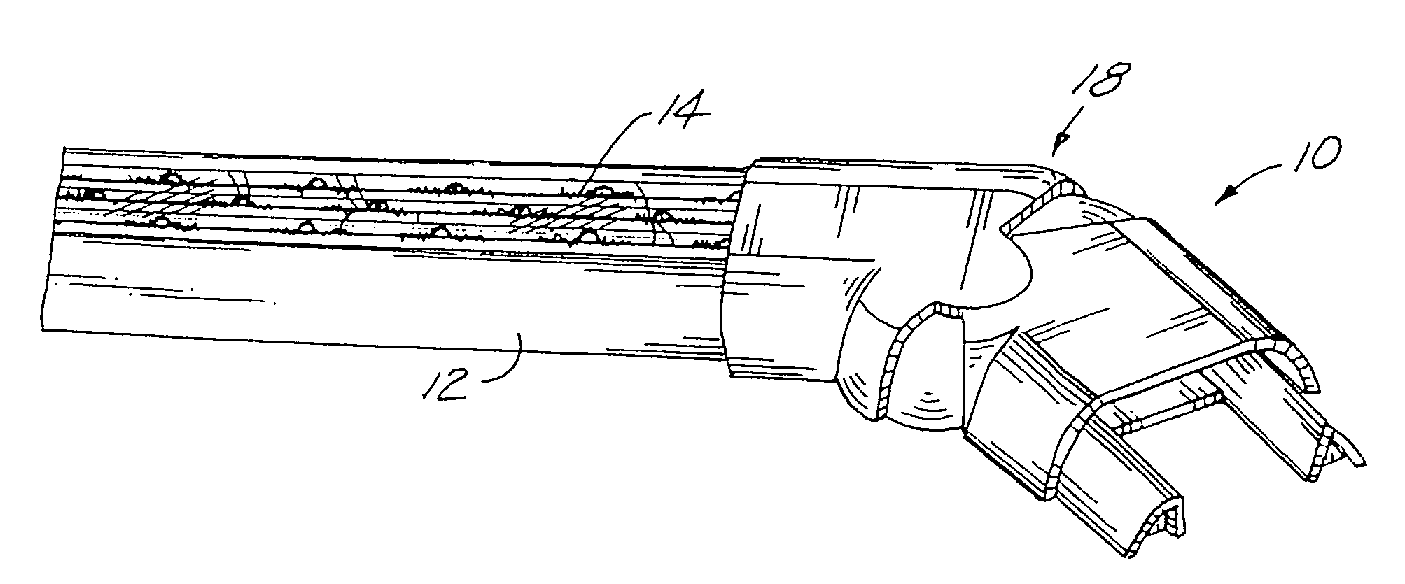
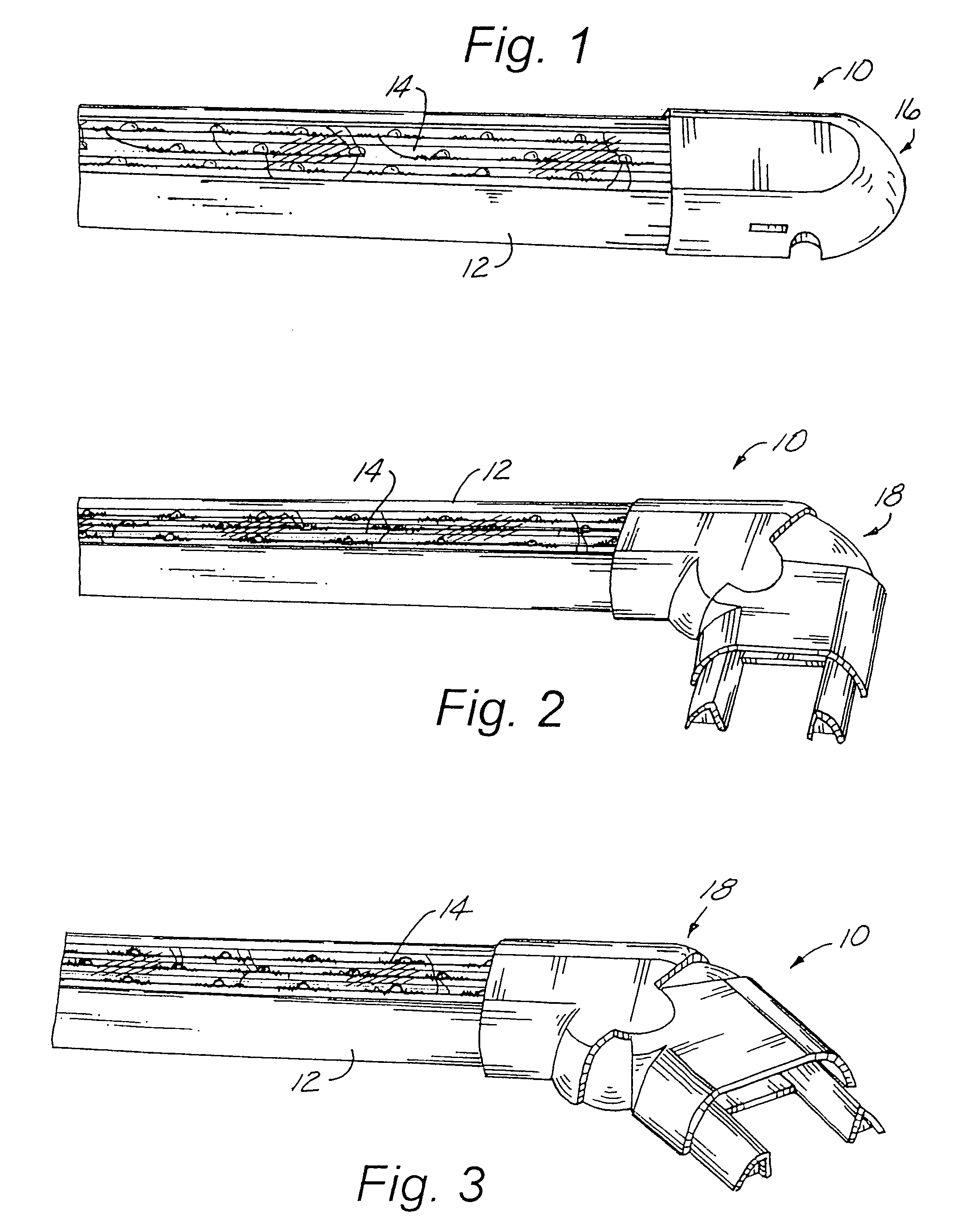
[0027]In the Figures, a channel light system 10 is shown. The channel light system 10 is a modular lighting system for use as a decorative lighting system. Preferably, the system 10 utilizes LED lighting, and is permanently or semi-permanently affixed to a commercial or residential structure such as a house; or to a boat, patio, cabinets, or other similar surfaces / articles. The system 10 is particular suited for holiday display lighting, such as Christmas, New Years, Fourth of July, birthdays, and the like.

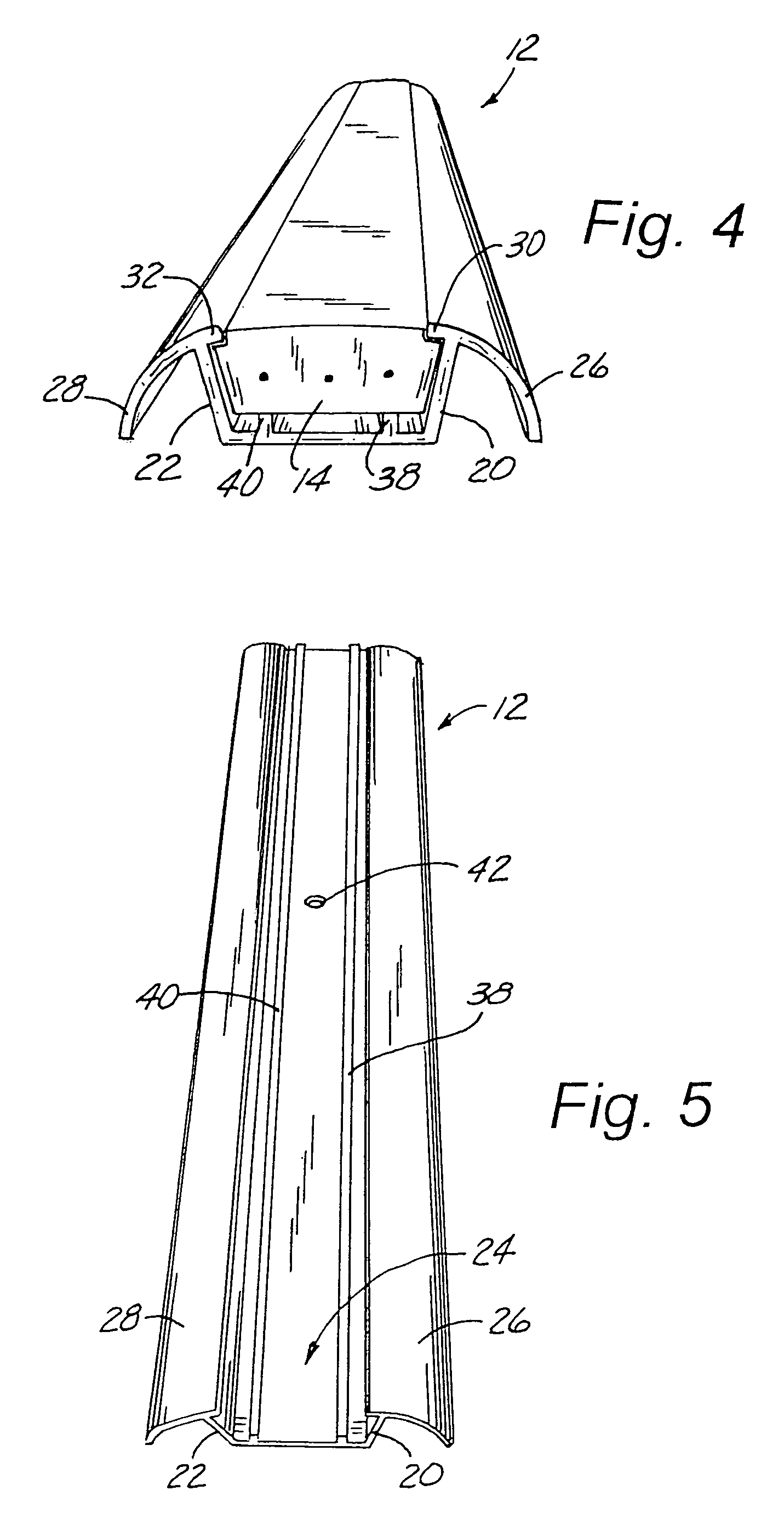
[0028]The system 10 is comprised of a channel 12, a rope light 14, a channel cap 16, and a pivot cap 18. FIG. 1 shows the channel 12 with the rope light 14 inserted therein, with the end cap 16 in place. This arrangement of the system 10 would be used at the terminal end of the system 10, to create a finished look. The channel 12 and rope light 14 feature matingly aligned profiles to form an interlocking connection when the rope light 14 is inserted into the channel 12.

[0029]FIGS....


PUM


Abstract

A lighting display system including a channel for mounting on a suitable display surface, a light secured within the channel, and an electrical means for powering the light. Preferably, the channel conforms to the shape of the light, which is a rope light, in order to releaseably retain the light. The channel can be interconnected with other channels, with caps including pivot caps, to form a lighting display suitable for mounting to an underlying surface of some types, such as a commercial or residential structure.

Description

BACKGROUND OF THE INVENTION[0001]The present invention relates to a lighting display system. In particular, the invention relates to a channel for mounting on a suitable display surface, a light secured within the channel, and an electrical means for powering the light.[0002]Lighting displays of the type used for seasonal holiday displays are well know in the art. These typically consist of a series of strings of lights strung together and connected to an electrical outlet. The lights normally are loosely affixed to the surface an article, such as a commercial or residential structure, boat, patio, and the like, with hooks, fasteners, or staples. The light are normally removed after the holiday and stored until the next holiday season.[0003]This creates a number of problems. The installation, removal, and storage of the lights is bothersome, time consuming, and in some cases dangerous. Installation often requires the use of a ladder, and due to seasonal considerations may take place...

Claims


Application Information

Patent Timeline
Patent Type & Authority Patents(United States)
IPC IPC(8): F21S4/00
CPCF21S4/00F21S4/002F21W2121/00F21S4/15
Inventor HANDSAKER, JERROLD
Owner INNOVATIVE LIGHTING LLC
Why Eureka
Try Eureka