Methodology and Application of technology to keep animal feeding systems running maximum feed availability for the entire crop to grow more evenly and healthily

a technology of animal feeding system and maximum feed availability, applied in the field of methodology and application of technology to keep animal feeding system running maximum feed availability for the entire crop to grow more evenly and healthily, can solve the problems of many animals without food, and achieve the effect of improving the efficiency and quality of feeding

Inactive Publication Date: 2016-10-20
PAUL TERRANCE BAKER JR
View PDF2 Cites 5 Cited by
  • Summary
  • Abstract
  • Description
  • Claims
  • Application Information

AI Technical Summary

Benefits of technology

[0005]The main purpose of the present invention is to provide a novel method of feeding poultry or the like and to keep animal feeding systems running maximum feed availability for the entire crop to grow more evenly and healthily, which can effectively guarantee synchronous feeding and improve the efficiency and quality of feeding.
[0006]Another object of the invention is to provide a method which will assure uniform distribution of feed to a large number of chickens or other poultry.
[0007]A further object of the invention is to make possible the deposit of feed at a plurality of stations simultaneously, whereby the tendency to crowd or injure weaker poultry away from the feed as deposited is substantially reduced or entirely eliminated.
[0008]The simple and effective structure avoid hurt of the poultry. It features both good efficiency and high practical value. The present invention attracts animal through their own natural curiosity and instinct drawing them to the control pan so it is emptied first. This product illuminates the control pan with a series of precisely placed, specifically colored low voltage LED lights. This lighting system is designed specifically for the grow out environment and can be retrofitted to existing systems as well as incorporated into new systems. The amperage required to operate the LED strand is very low, this allows the system to be powered by a bulb outlet and remain very bright even when room lights have been dimmed to 2% of normal illumination (a key product requirement for conventional poultry rearing.)

Problems solved by technology

Because of uneven animal distribution, varied lighting, water availability, temperature variations, and other factors feed pans in the center of the house often become empty before the end “control pan” does, leaving many animals without food until the end pan is eventually emptied.

Method used


Image

  • Methodology and Application of technology to keep animal feeding systems running maximum feed availability for the entire crop to grow more evenly and healthily
  • Methodology and Application of technology to keep animal feeding systems running maximum feed availability for the entire crop to grow more evenly and healthily
  • Methodology and Application of technology to keep animal feeding systems running maximum feed availability for the entire crop to grow more evenly and healthily

Examples


Embodiment Construction

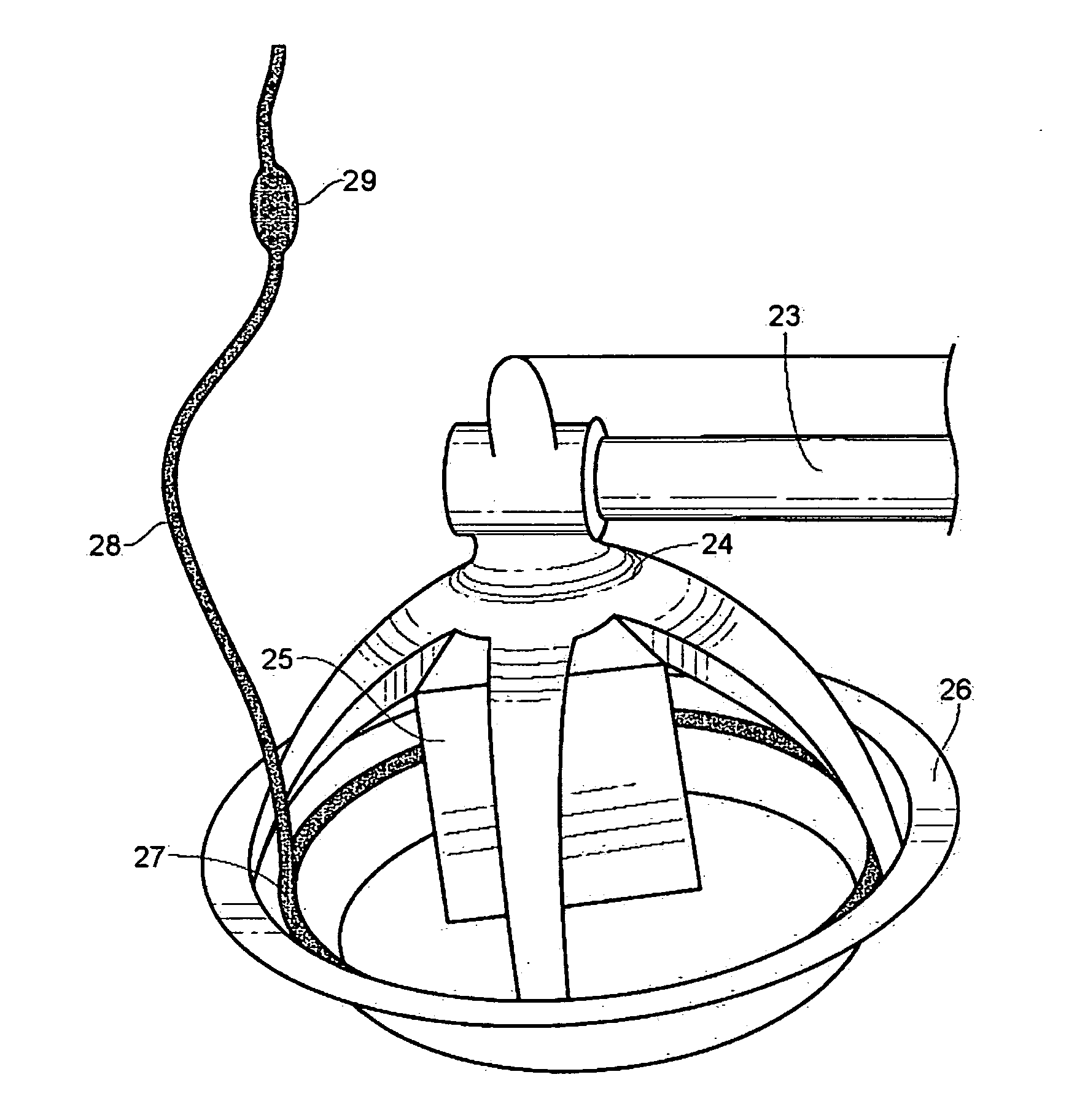
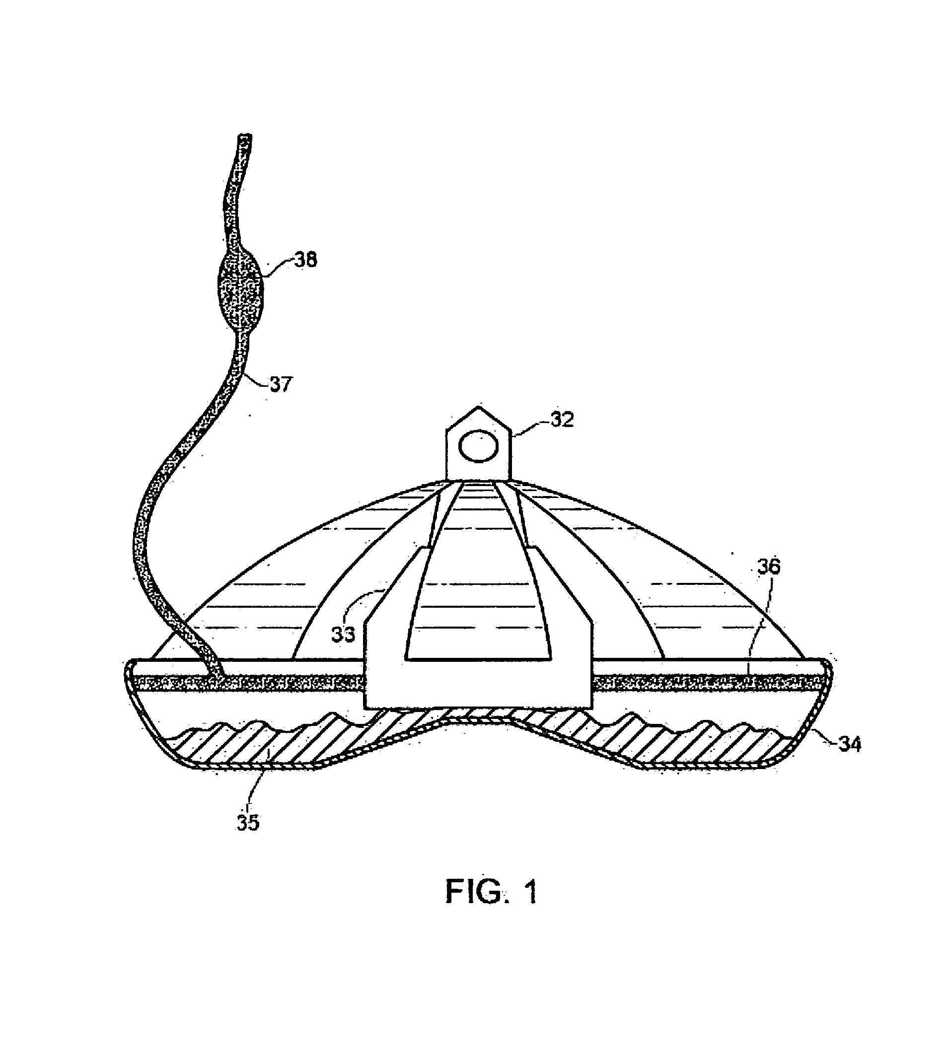
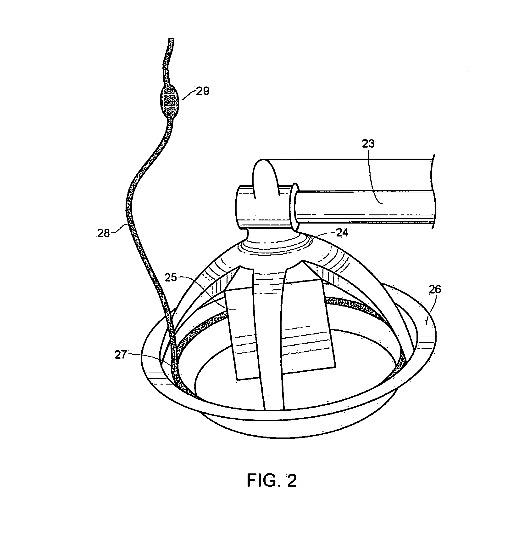
[0016]FIG. 1 is representative of a typical feed control pan with a feed delivery line 32 which passes through the opening with a slot for the drop tube 39 which deepens into the control box which houses the control switch 33 feed falls through the control box into the feed pan 34 until the pan is full and feed 35 begins to back up into the control box 33 when enough feed backs up it triggers the control switch which turns off the auger motor 20 stopping feed from moving down the line feed line 13. The low voltage LED strip rope light 36 can be installed into existing feed systems or designed as part of a new system. The low voltage LED strip rope light illuminates the feed in the control pan as long as any lights are on in the house; encouraging birds to consume feed from this before any other pans. The control pan illumination system is enclosed in flexible, and rectangular shaped eco-friendly PVC tube (but not limited to this type of enclosure and systems can be of any shape or r...


PUM


Abstract

The present invention provides a method, wherein a lighting system consisting of a series of LED lights is configured through a feed conveying pan. The conveying pan also known as the “control pan” comprises of a pan and a low voltage LED strip rope light configured normally along the inside of the pan. The LED strand is itself powered by a bulb due to the very low amperage needed to operate it. With the help of a power supply, the LED lights illuminate the control pan causing a sudden interest in the animals to come closer to the control pan. Thus, the control pan gets emptied first ensuring feed availability to the entire house.

Description

FIELD OF INVENTION[0001]This invention relates to the Methodology and Application of technology to keep animal feeding systems running maximum feed availability for the entire crop to grow more evenly and healthily.BACKGROUND ART[0002]Conventional meat poultry are reared in an automated environment with all conditions of their wellbeing controlled by computer systems. Maintaining feed availability to the entire flock consistently through the house is vital in maintain the growth and health of the animals.[0003]Feed is delivered through long tubes (often over 500 ft in length) via an internal screw auger. This system is controlled by a feed pan switch located at the very end of the line; when the feed is removed from this end pan the entire line comes on supplying feed to all the subsequent pans in the house via the auger until the control pan is once again full turning off the line. Because of uneven animal distribution, varied lighting, water availability, temperature variations, a...

Claims


Application Information

Patent Timeline
Patent Type & Authority Applications(United States)
IPC IPC(8): F21S4/00F21V33/00A01K39/00
CPCA01K39/00F21W2131/40F21V33/006A01K39/0125
Inventor BAKER, JR., PAUL T.
Owner PAUL TERRANCE BAKER JR
Why Eureka
Try Eureka