

Method and apparatus for non-destructive testing of components of gas turbine engines made of monocrystalline materials
a gas turbine engine and monocrystalline material technology, applied in the direction of vibration measurement in solids, instruments, static/dynamic balance measurement, etc., can solve the problems of non-destructive material testing using ultrasound, inspection of components made of monocrystalline materials, and the interior of a component has been known for quite a long tim
- Summary
- Abstract
- Description
- Claims
- Application Information
AI Technical Summary
Benefits of technology
Problems solved by technology
Method used
Image

Examples
Embodiment Construction
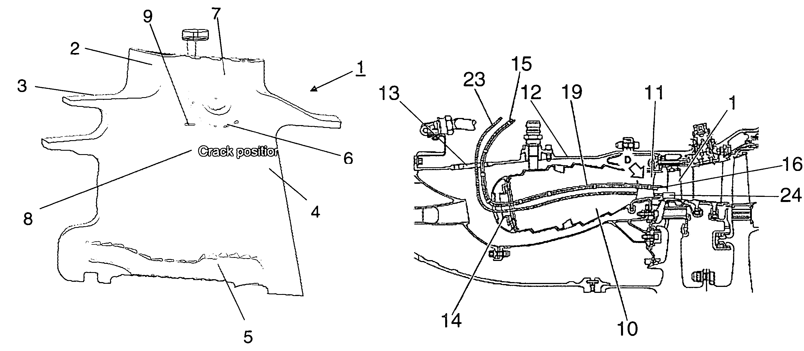
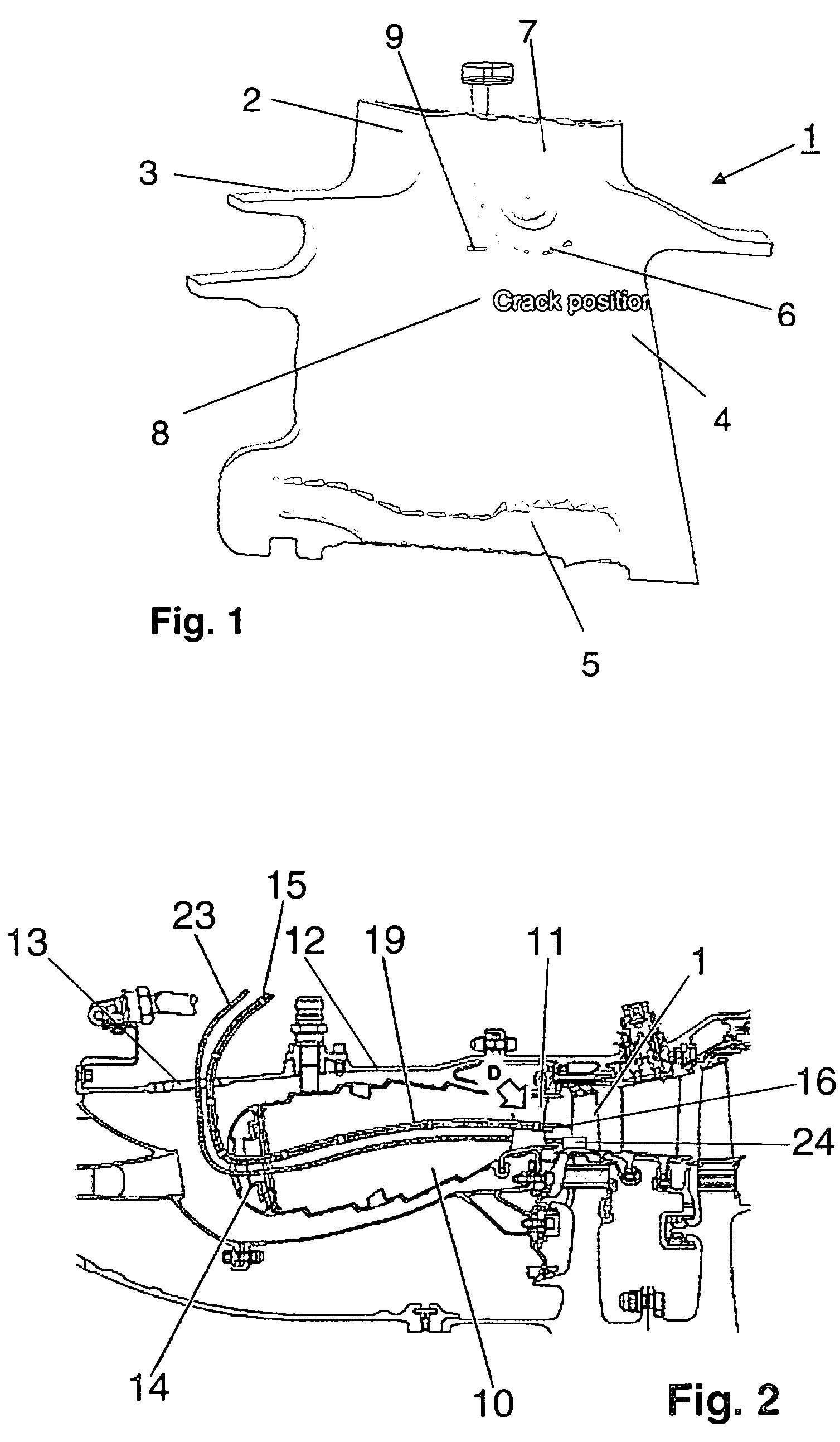
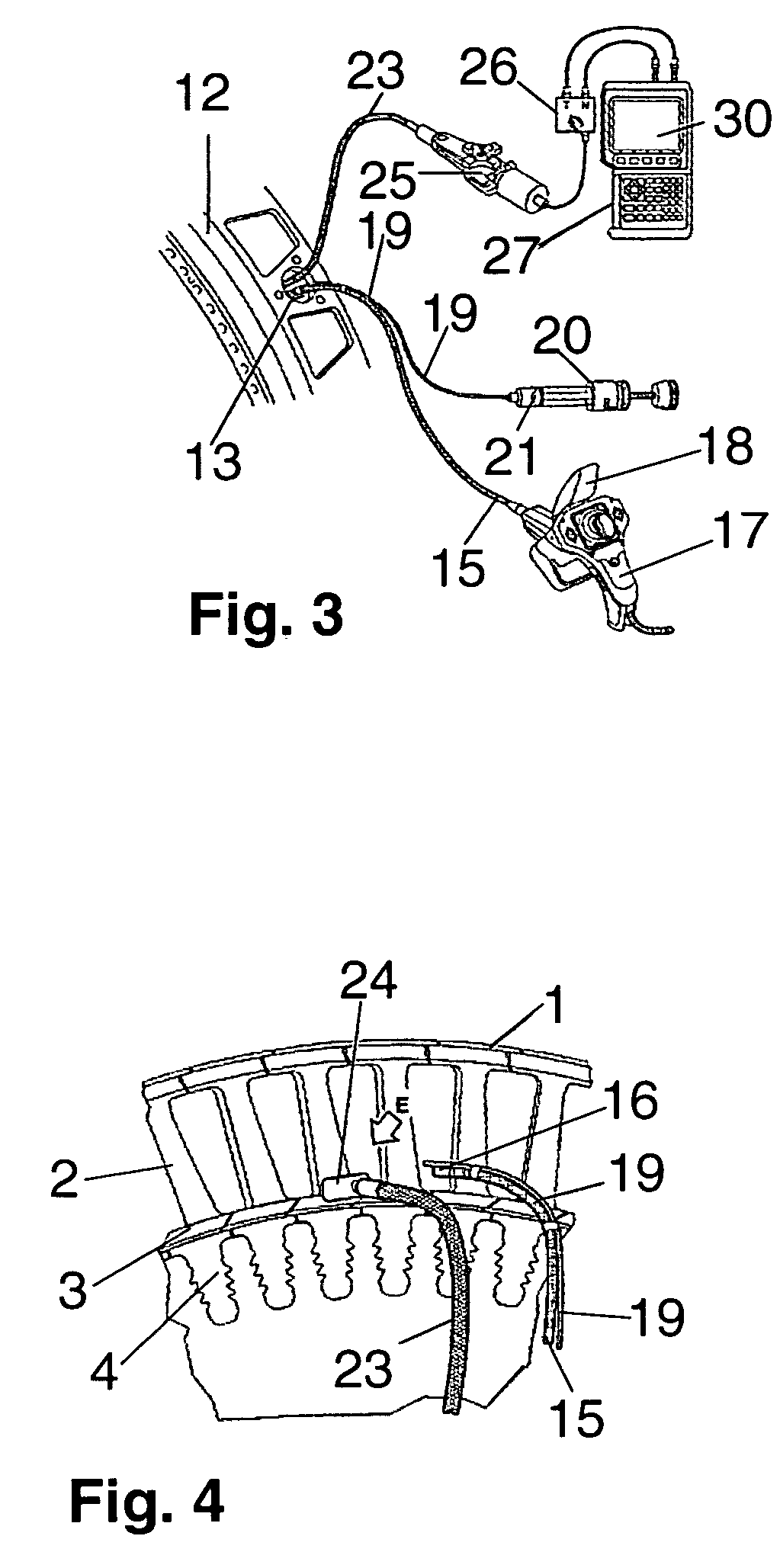
[0007]The present invention, in a broad aspect, provides an inspection method and an inspection apparatus for components made of monocrystalline materials, and in particular, for crack inspection of turbine blades of gas turbine engines, which ensure a meaningful, safe inspection of the components with a minimum time investment.
[0008]It is a particular object of the present invention to provide a solution to the above problems by a method in accordance with the features described herein and by an inspection apparatus designed in accordance with the features also described herein. Further features and advantageous embodiments of the present invention will be apparent from the present description.
[0009]An essential inventive feature is that the inspection of components made of monocrystalline materials by longitudinal ultrasonic waves is performed within the engine, i.e., in the installed state of the components. It was found that it is possible to obtain reliable, sufficiently intens...
PUM
| Property | Measurement | Unit |
|---|---|---|
| temperature | aaaaa | aaaaa |
| ultrasonic probe | aaaaa | aaaaa |
| transmission | aaaaa | aaaaa |
Abstract
Description
Claims
Application Information