Floor cleaning machine

a floor cleaning machine and cleaning technology, applied in the direction of carpet cleaners, cleaning equipment, cleaning machines, etc., can solve the problems of heavy weight, difficult to discard collected debris, and a large portion of the dirt delivered by the machine will not reach the dirt container, so as to achieve the effect of convenient for the operator

Inactive Publication Date: 2009-07-07
HAKO WERKE GMBH & CO
View PDF2 Cites 16 Cited by
  • Summary
  • Abstract
  • Description
  • Claims
  • Application Information

AI Technical Summary

Benefits of technology

[0005]A primary object of the present invention is to configure a floor-cleaning machine such that the handling of collected dirt in dual, separate containers is more convenient for the operator, and avoids direct operator contact with the dirt during removal, transportation and emptying of the containers. Yet, more of the dirt recovered by the machine is placed in the dirt containers.

Problems solved by technology

The larger, single containers may extend transversely substantially over the entire width of the machine, in which case they are bulky and heavy.
Because of the weight and size of such single hoppers, discarding collected debris may be difficult.
Despite the close side-by-side arrangement of the dirt containers on the frame, it is inevitable that a portion of the dirt delivered by the machine will not reach the dirt containers and will fall between or around the dirt containers.
The outer surfaces of the dirt containers thus become dirty.
Furthermore, dirt accumulates on the carrying handles during use.
For that reason, the operator, in the process of emptying the containers, may soil his hands and his clothing due to the accumulation of dirt on the outer surfaces and handle of the dirt containers.
The accumulation of dust on the solid bottom surface of the container frame interferes with locating the containers accurately in the use position, requiring the operator to separately clean the bottom surface of the dirt container frame at regular intervals.

Method used


Image

  • Floor cleaning machine
  • Floor cleaning machine
  • Floor cleaning machine

Examples


Embodiment Construction

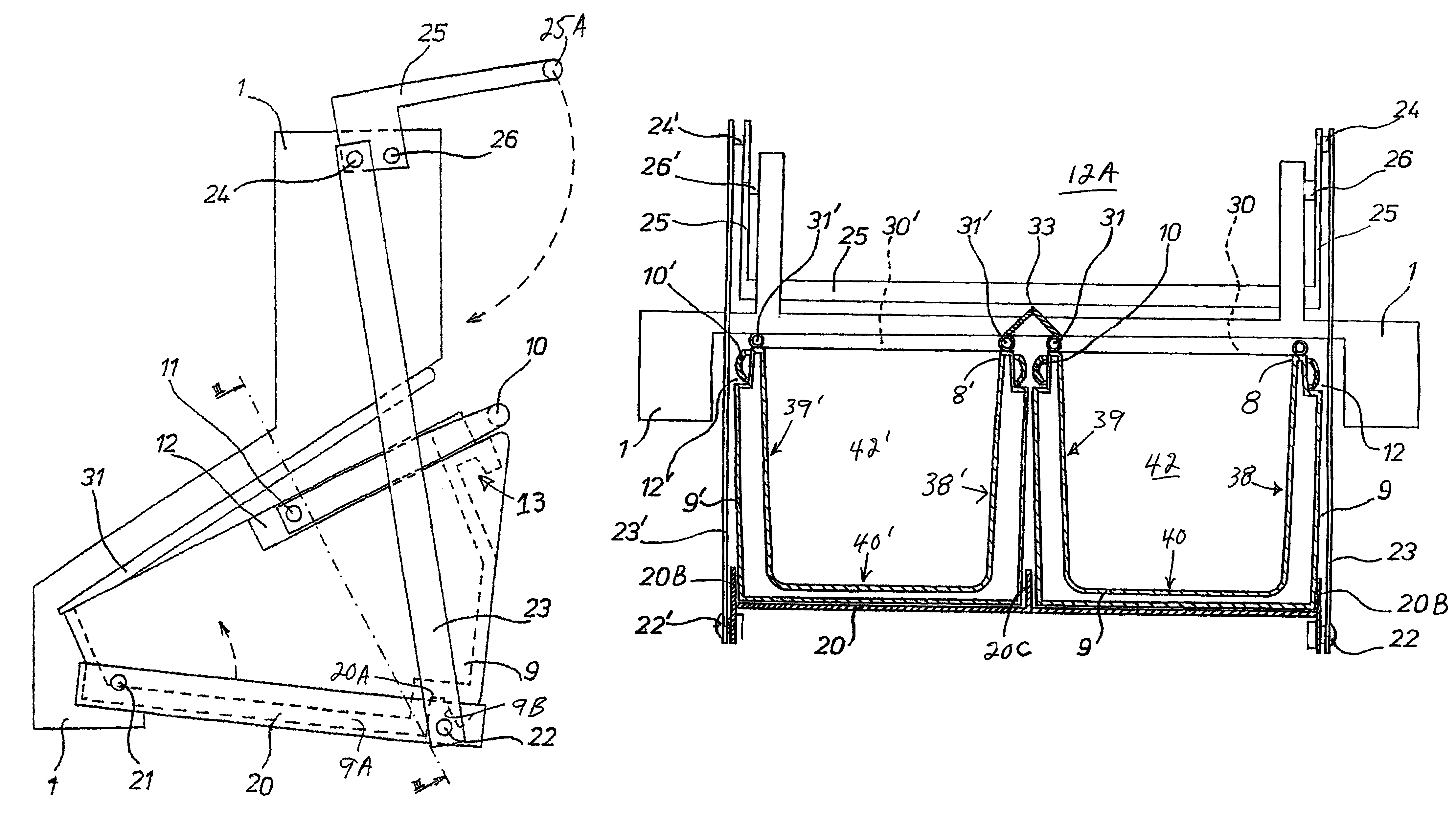
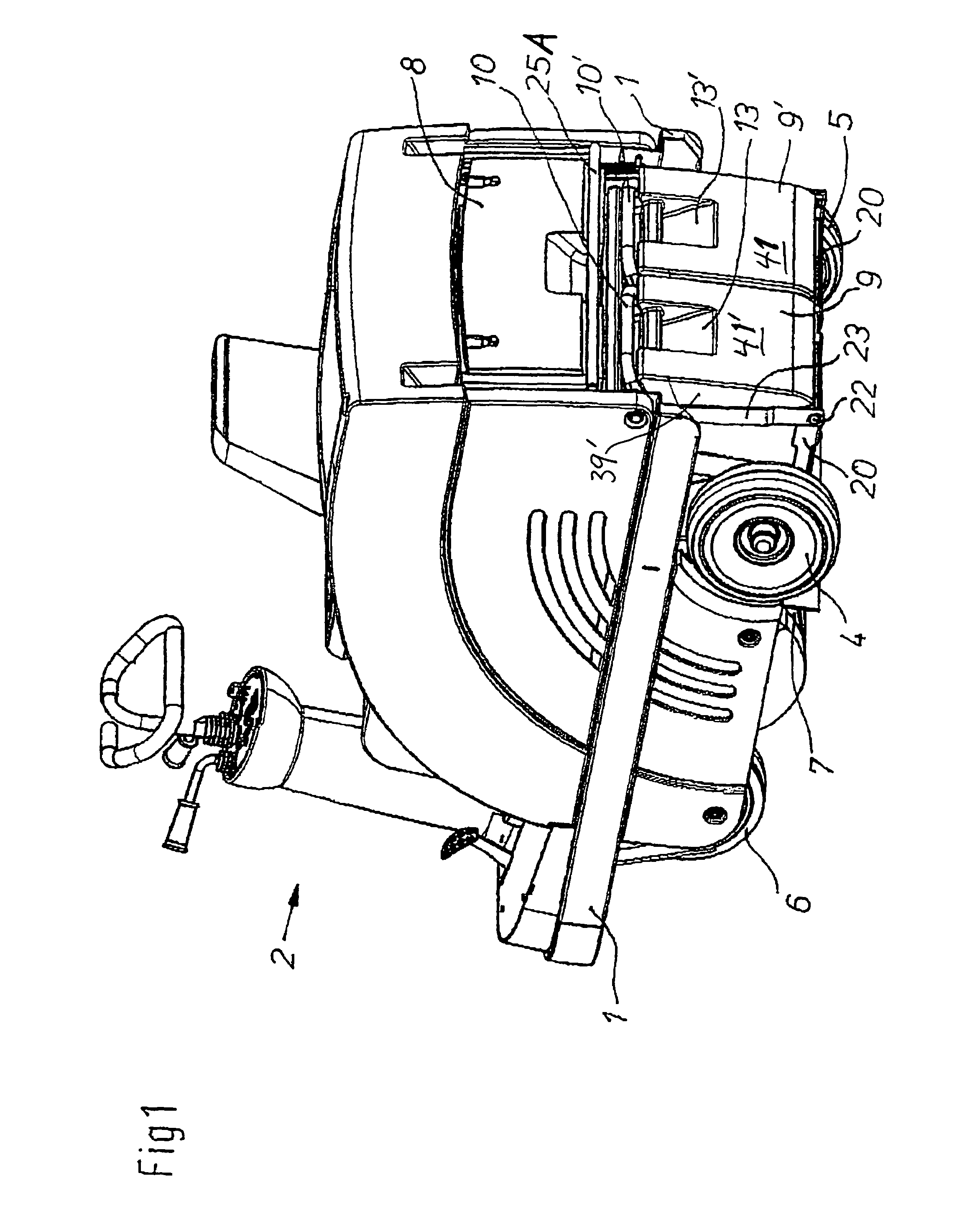
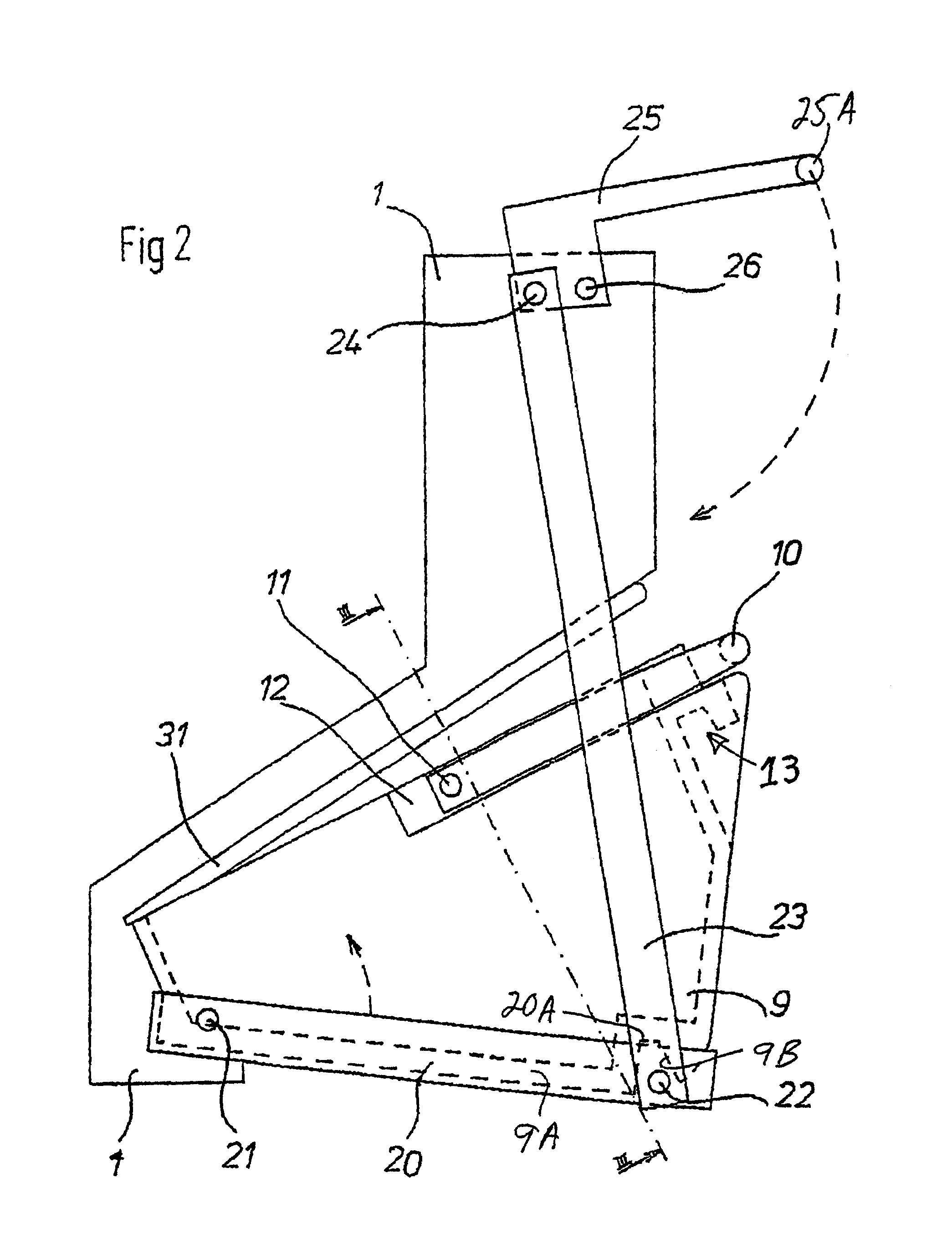
[0023]A floor-cleaning machine illustrated in FIG. 1. The machine is of a known type of construction and has a chassis 1 or main frame, on which there are mounted rear wheels 4 and 5 and a front wheel 6. The front wheel 6 is driven and steerable by the operator. On the chassis, there is a forward operator's station 2 which includes a driver's seat and the controls necessary for operation of the floor-cleaning machine. The floor-cleaning machine has a rotary-driven roller or cylindrical brush 7, which, in operation, contacts the floor to be cleaned, and picks up dust, dirt and other debris in an overhead motion.

[0024]The dirt is transported by the brush 7 and an air stream generated by an impeller (not shown) which creates suction to the rear of the brush. The dirt is carried via a dirt transfer duct 12A through dirt delivery openings in a wall of the outer casing, and thence into inlet openings of dirt containers 9, 9′, to be described. The air stream with entrained dirt and dust tr...


PUM


Abstract

A floor-cleaning machine which can be driven over the floor, includes a driven brush for sweeping the floor to be cleaned. The brush picks up dirt and debris from the floor and carries it, assisted by forced air flow, in an overhead motion and through a transfer duct to a pair of dirt containers in the form of buckets located side-by-side at the rear of the machine. A manual linkage at the rear of the machine moves a pivoted carrier frame which holds the dirt containers, between a raised use position in which the upper rims of the dirt containers are sealed to the machine for collection of debris, and a lowered access position for removal of the containers. Each container is independently accessible for emptying, and includes a bail-type handle pivotally attached such that a bucket, the opening of which faces forwardly and upwardly in the use position, extends generally horizontal when removed, to avoid spillage. Each container has a recess adjacent the inlet opening for receiving the handle in the operating position.

Description

FIELD OF THE INVENTION[0001]The present invention relates to floor cleaning machines; and more particularly to powered sweepers having a forward cylindrical brush which delivers dirt and debris, in cooperation with a forced air stream, to a collection hopper or container in the rear of the machine.BACKGROUND OF THE INVENTION[0002]Floor sweepers are known which have bucket-type dirt pick-up containers. Some machines have containers of integral construction, others have two separate dirt containers. The larger, single containers may extend transversely substantially over the entire width of the machine, in which case they are bulky and heavy. In order to remove the dirt accumulated within the single container, the operator must remove it manually, carry the container and contents to a disposal area, and empty it by turning it over. Typically, the operator may shake the container to remove finer particles. Because of the weight and size of such single hoppers, discarding collected debr...

Claims


Application Information

Patent Timeline
Patent Type & Authority Patents(United States)
IPC IPC(8): E01H1/04A47L11/24A47L11/40
CPCA47L11/4013A47L11/24
Inventor PETERS, MARCOKATENHUSEN, HENRICH
Owner HAKO WERKE GMBH & CO
Why Eureka
Try Eureka