Cannula for percutaneous minimally invasive cannulation of the vena cava

a cannula and vena cava technology, applied in the field of cannulas for percutaneous minimally invasive cannulation of the vena cava, can solve the problems of difficult or even impossible minimally invasive surgery, and achieve the effects of reducing the time to prepare the surgical region for surgery, convenient for the operator, and tight protection

Pending Publication Date: 2021-12-02
MEDINICE SA
View PDF1 Cites 0 Cited by
  • Summary
  • Abstract
  • Description
  • Claims
  • Application Information

AI Technical Summary

Benefits of technology

[0020]The main advantage of the solution according to the invention is to provide tight protection during minimally invasive cardiac surgery. The cannula can be used in various operating techniques. It is convenient for the operator and significantly reduces the time to prepare the surgical region for surgery. In addition, the use of the cannula either eliminates the need for cutting at all or makes the cut minimal, even smaller than the diameter of the cannula.
[0021]The conical end of the cannula allows convenient placement of the cannula inside the vessel and then easy insertion into the next incision. Removing the cone will extend the balloon inflating port, which port is equipped with a short hose.
[0022]The design of the cannula allows you to create several versions adapted to different needs, depending on which operating technique will be chosen by the operator, ranging from the simplest and cheapest version to the most equipped version intended for use in more demanding cases.

Problems solved by technology

However, it can be very difficult or even impossible in minimally invasive surgery, which involves access to the heart and valve under the control of an endoscopic camera using special long tools.

Method used


Image

  • Cannula for percutaneous minimally invasive cannulation of the vena cava
  • Cannula for percutaneous minimally invasive cannulation of the vena cava
  • Cannula for percutaneous minimally invasive cannulation of the vena cava

Examples


first embodiment

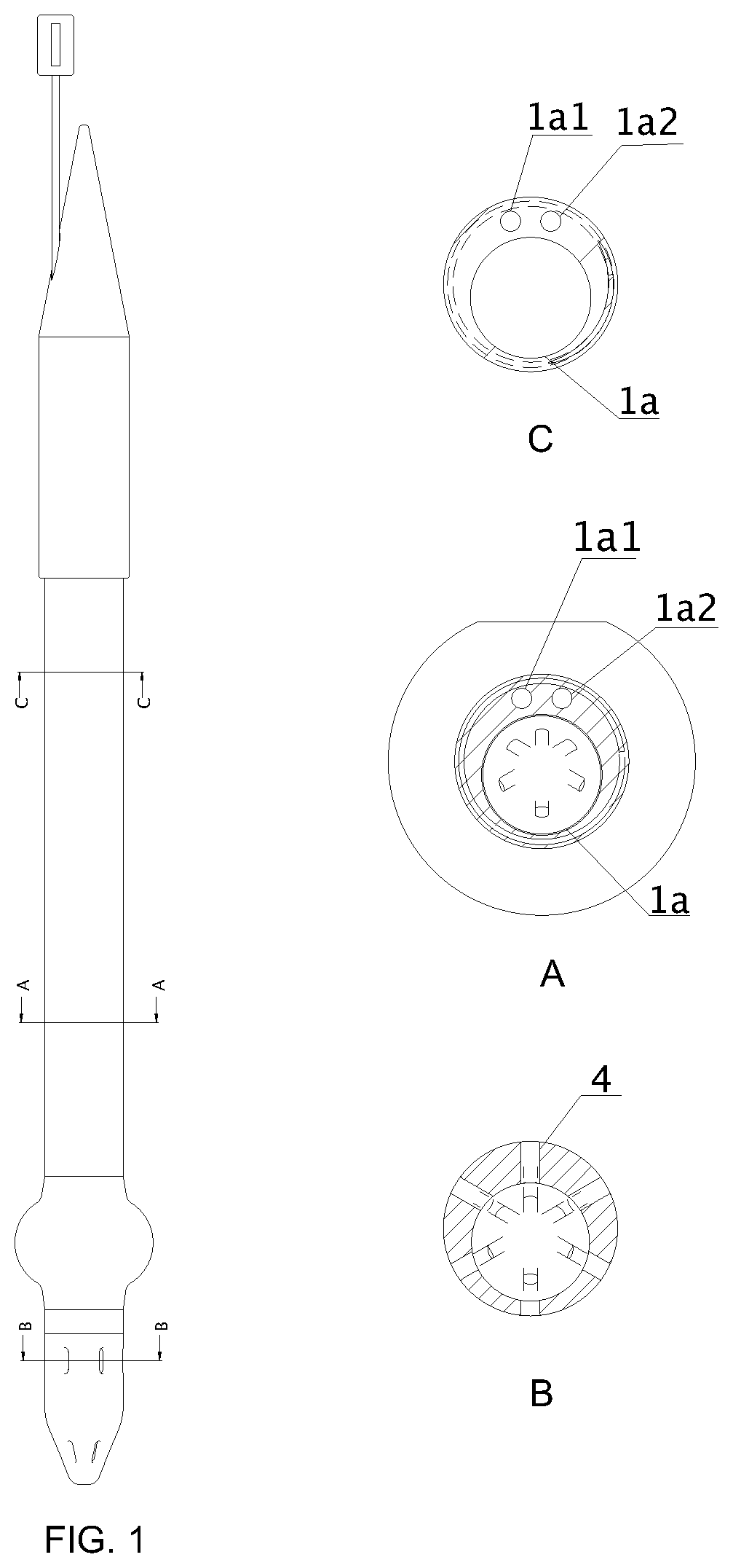
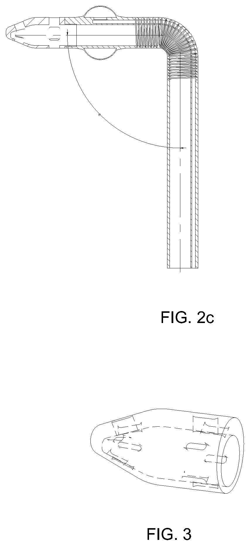
[0039]In the first embodiment shown in FIG. 1, the cannula is a flexible tube 1 made of plastic having three longitudinal chambers, a main chamber 1a, a first lateral chamber 1a1 and a second lateral chamber 1a2, and from the distal side a round end 2 in which there are longitudinal holes 4 allowing venous blood to flow freely inside the cannula tube 1. The holes 4 are evenly distributed around the perimeter of the round end 2. Alternatively, the holes 4 can be distributed evenly on the circumference of the round end 2 in two rows and shifted in phase between rows.

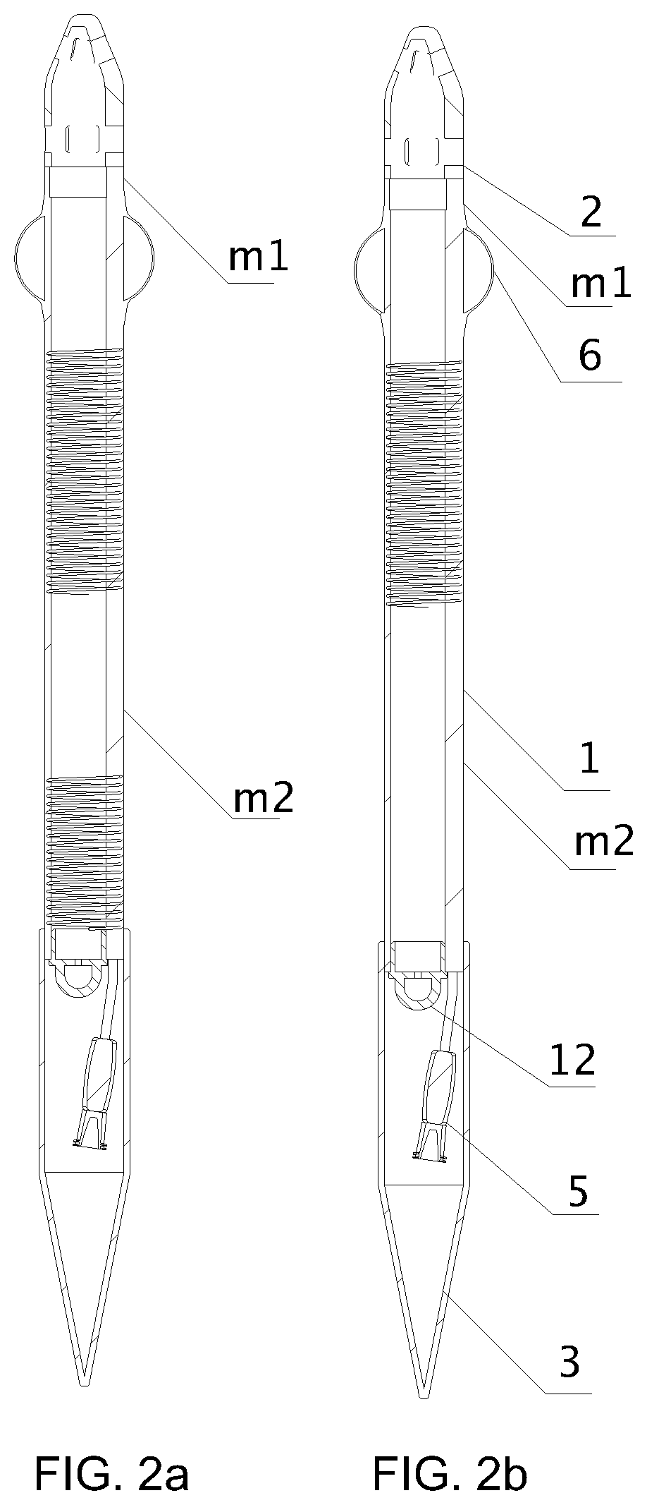
[0040]Behind the round end 2 there is a soft section m1 bounded from the proximal side with a balloon 6, followed by a reinforced section, the fragment of which is bent at an angle of approximately 90°. The reinforced section then passes into the soft section m2, terminated from the proximal side with the cone 3, sealing the cannula light tightly. Inside the cone 3 there is a port 5 for inflating the balloon 6 and a valve ...

second embodiment

[0042]In the second embodiment shown in FIG. 2, the reinforced section of the tube 1 is divided by the soft section m2, on which a clamp is applied. Whereas cone 3 is located at the proximal end of the reinforced section.

[0043]The first use of the cannula is that the surgeon, through the incision in the intercostal space gets into the area of the vena cava and the round end 2 is inserted through the incision of the vein into the lumen, after which it is attached using surgical methods. The next step is to remove the stiffener 8 from the second lateral chamber 1a2. Then another incision in the chest wall is made and a surgical tool is inserted into the chest near the operating region, after which the cone 3 is gripped with the tool and leads to a transcutaneous incision in the chest wall, and then cone 3 is pushed out of the body through the percutaneous an incision in the chest so that the surgeon can use a soft cannula with a conical end outside of the patients body. The cone 3 is ...


PUM


Abstract

A cannula comprising a plastic tube having three longitudinal chambers, including a main chamber, a first lateral chamber and a second lateral chamber, and at least one reinforced section ensuring constant internal diameter, wherein the cannula is equipped from the distal side with a round end narrowing towards the end, in which there are longitudinal holes of a size enabling free venous blood flow, and a balloon. A fragment of the reinforced tube section located below the balloon is bent under an angle α of approximately 90°. From the proximal side, the tube ends with a flexible cone, sealing the cannula tightly, inside which there is a valve closing the main chamber and a port for inflating the balloon connected to the first lateral chamber.

Description

CROSS REFERENCE TO RELATED APPLICATIONS[0001]This application claims the benefit of European Patent Application No. EP 20177271.2, filed on May 28, 2020, the contents of which are hereby incorporated by reference.TECHNICAL FIELD[0002]The object of the invention is a cannula for percutaneous minimally invasive cannulation of the vena cava.BACKGROUND ART[0003]Cardiosurgical operations require releasing the heart from the task of pumping blood, and thus connecting to the patient's bloodstream an artificial lung heart in the extracorporeal circulation system. This device performs mechanical work by generating pressure to allow blood to be pumped through peripheral vessels and oxygenate venous blood. The extracorporeal circulation system is a device with cannulas connected to the main vessels of the heart.[0004]In recent years, minimally invasive methods in which the whole procedure is carried out through a small incision of the skin in the intercostal space, are chosen more often.[0005]...

Claims


Application Information

Patent Timeline
Patent Type & Authority Applications(United States)
IPC IPC(8): A61B17/34A61B17/00
CPCA61B17/3423A61B17/00234A61B2017/3486A61B2017/3425A61B2017/3447A61B2017/00243A61M25/0023A61M25/0052A61M25/1002A61M25/0068A61B17/3421A61B2017/22051A61B2017/00331A61B17/12109A61B17/12136A61M1/3659A61B17/3478A61B17/3496A61M25/007A61M25/0041A61M25/04A61M1/3666A61M25/005A61M2205/586
Inventor CHOUDHARY, SANJEEVSUWALSKI, PIOTRMAKUCH, MARTAOLSZEWSKI, JACEK
Owner MEDINICE SA
Why Eureka
Try Eureka