Stationary exercise device

a stationary exercise and exercise technology, applied in the direction of cardiovascular exercise devices, gymnastic exercise, sport apparatus, etc., can solve the problems of suitably increasing the moving stroke of the typical exercise device, not suitably increasing not suitably increasing or adjusting the moving stroke of the typical exercise device, etc., to achieve the effect of increasing the moving strok

Inactive Publication Date: 2009-07-07
CHUANG JIN CHEN +1
View PDF11 Cites 62 Cited by
  • Summary
  • Abstract
  • Description
  • Claims
  • Application Information

AI Technical Summary

Problems solved by technology

However, normally, the middle portion of the foot supports is pivotally coupled to the upwardly extending frame member such that the middle portion of the foot supports is pivoted relative to the base support device but may not be moved cyclically or in reciprocating relative to the base support device, and such that the moving stroke of the typical exercise devices may not be suitably increased.
However, the middle portion of the foot supports is only pivoted relative to the base support device but may not be moved cyclically or in reciprocating relative to the base support device, and such that the moving stroke of the typical exercise devices may not be suitably increased.
However, the middle portion of the foot supports is only pivotally coupled to the handles, and may not be moved cyclically or in reciprocating relative to the base support device such that the moving stroke of the typical exercise devices may not be suitably increased or adjusted.
However, similarly, the foot supports is only pivotally coupled to the handles, and may not be moved cyclically or in reciprocating relative to the base support device such that the moving stroke of the typical exercise devices may not be suitably increased or adjusted.
However, the handles are located closer to the users, and are pivotally coupled to the upright support and may also be moved cyclically relative to the upright support of the base support device such that the handles will also be moved cyclically relative to the upright support and such that the handles may not be suitably or easily grasped and handled by the users.
However, the foot supports are only coupled to the upright support or the base support such that the foot supports may only be stepped or moved up and down relative to the base support device, but may not be stepped or moved elliptically relative to the upright support of the base support device.

Method used


Image

  • Stationary exercise device
  • Stationary exercise device
  • Stationary exercise device

Examples


Embodiment Construction

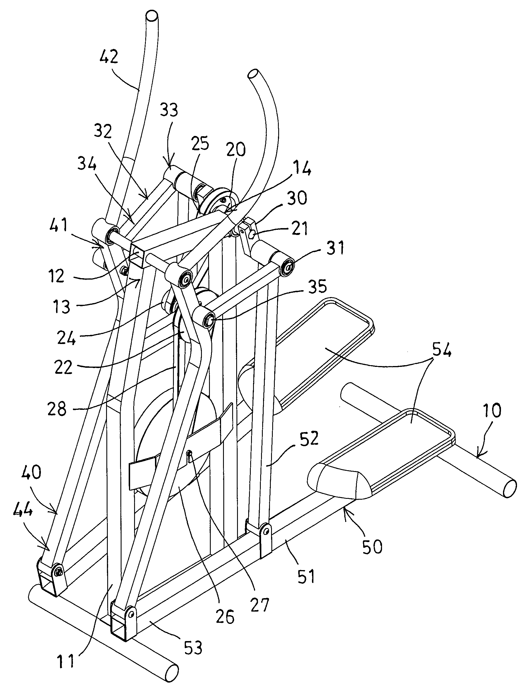
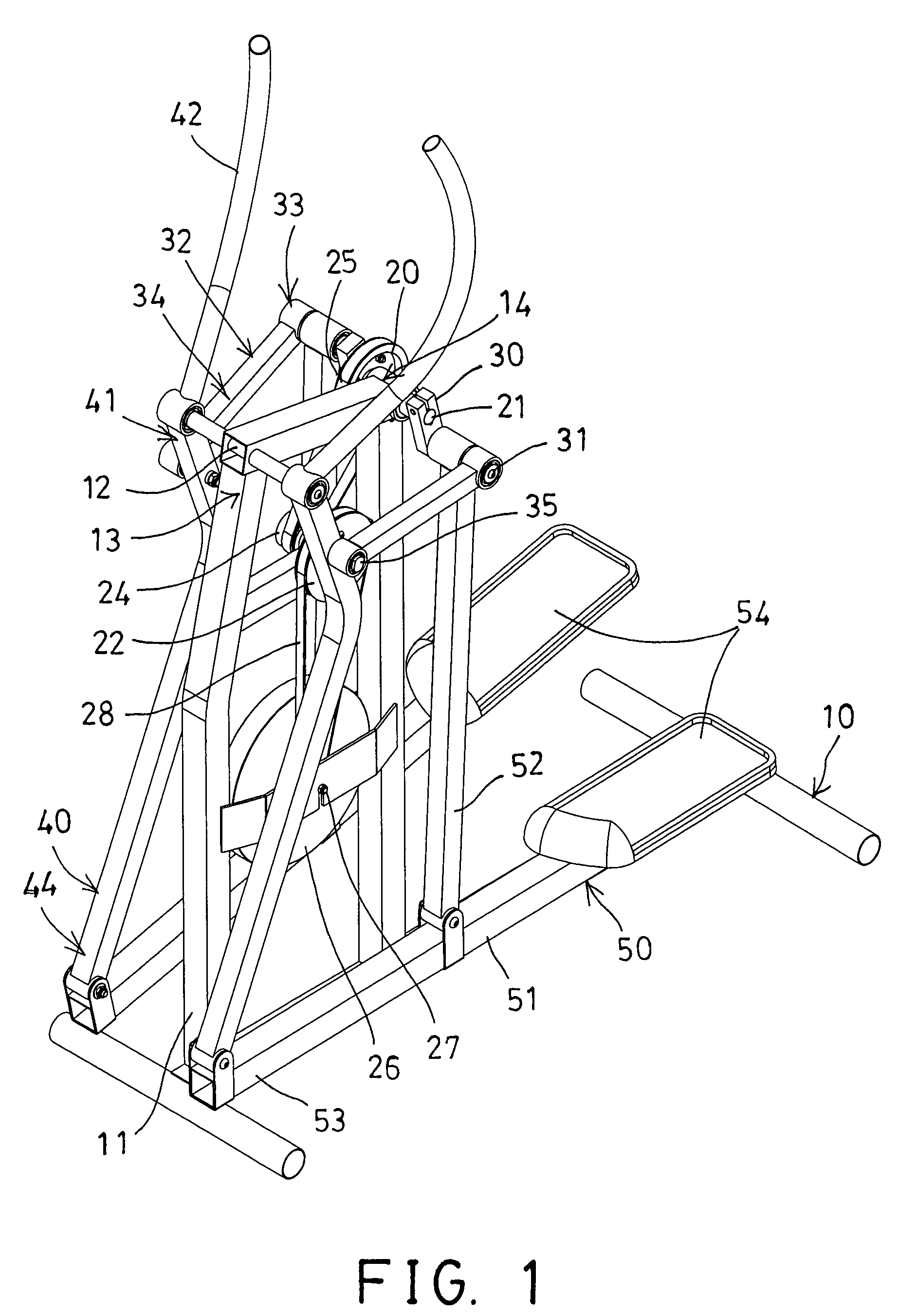
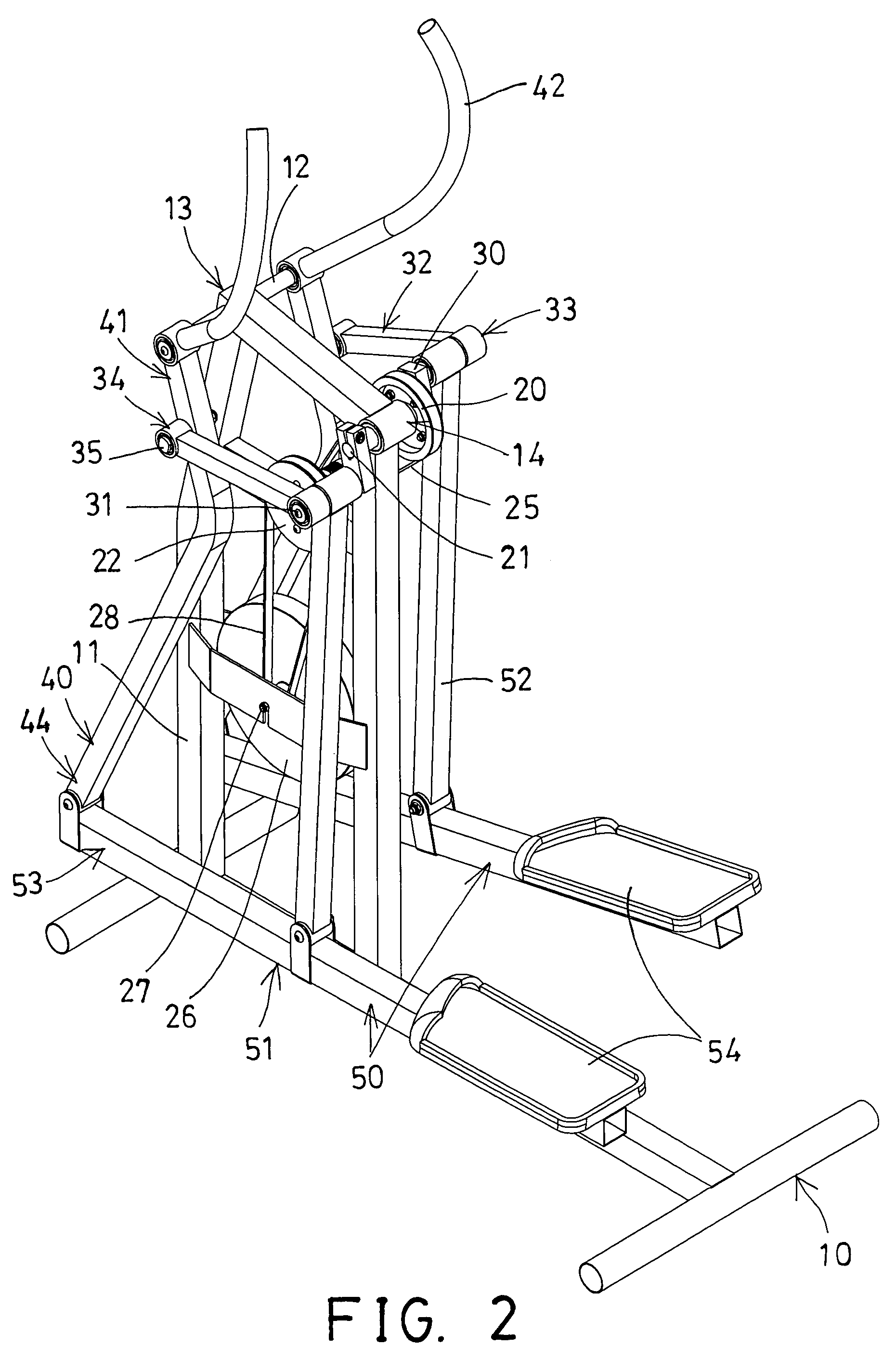
[0030]Referring to the drawings, and initially to FIGS. 1-5, an exercise device 1 in accordance with the present invention comprises a base 10, an upright support 11 extended upwardly from the base 10, a spindle 12 disposed or provided on the front portion 13 of the upright support 11, a rotary member or pulley or wheel 20 rotatably attached to the rear portion 14 of the upright support 11 with a shaft 21, another wheel or pulley or rotary member 22 rotatably attached to the middle portion of the upright support 11 with an axle 23, a further wheel or rotary member or pulley or follower 24 attached or secured to the axle 23 and, moved in concert with the axle 23, and the follower 24 is coupled to the wheel 20 with a coupling device 25, such as a sprocket-and-chain coupling device or a gearing coupling device (not shown), or a belt 25 for allowing the follower 24 and the rotary member 22 to be rotated or driven by the wheel 20.

[0031]A weight or flywheel 26 may further be provided and ...


PUM


Abstract

An exercise device includes two cranks rotatably coupled to a rear portion of a upright support and each having a pivot rod, two handles having a middle portion pivoted to a front portion of the upright support with a spindle, two foot supports pivotally coupled to the handles and each having a middle portion pivotally coupled to the pivot rod of the cranks with a link, and two levers pivotally coupled to the pivot rod and the handle and spaced away from the spindle for forming a polygonal coupling structure and for allowing the foot supports to be controlled by both the cranks and the link and the handles, and for allowing the foot supports to be moved elliptically relative to the upright support of the base.

Description

BACKGROUND OF THE INVENTION[0001]1. Field of the Invention[0002]The present invention relates to a stationary exercise device, and more particularly to an elliptical exercise device including an arrangement for allowing the exercise device to have an increased or different moving stroke.[0003]2. Description of the Prior Art[0004]Typical exercise devices, such as stepping exercisers comprise a pair of handles pivotally attached to an upwardly extending frame member of a base support device, and a pair of foot supports pivotally coupled to the handles and arranged for allowing the foot supports to be stepped or moved up and down relative to the base support device.[0005]For example, U.S. Pat. No. 5,290,211 to Stearns discloses one of the typical exercise devices also comprising a pair of handles pivotally attached to an upwardly extending frame member of a base support device, and a pair of foot supports pivotally coupled to the handles, and a pair of force resisting device pivotally ...

Claims


Application Information

Patent Timeline
Patent Type & Authority Patents(United States)
IPC IPC(8): A63B22/00A63B69/16
CPCA63B22/001A63B22/0664A63B2022/0682
Inventor CHUANG, JIN CHENCHUANG, LUNG FEI
Owner CHUANG JIN CHEN
Why Eureka
Try Eureka