Tool having an ejection assembly, a method for making such a tool, and a method for ejecting a formed object from a tool

a tool and assembly technology, applied in the field of tool and tool formation strategy, can solve the problems of high cost and high inefficiency, increased cost and inefficiency in direct proportion, and undesirable increase of overall cost and time of production

Inactive Publication Date: 2009-07-21
EDMOND DANTES HLDG LLC
View PDF79 Cites 3 Cited by
  • Summary
  • Abstract
  • Description
  • Claims
  • Application Information

AI Technical Summary

Problems solved by technology

While this traditional approach does allow a tool to be created, it is costly and highly inefficient.
Particularly, this cost and inefficiency increases in direct proportion to the size of the desired tool.
By way of example and without limitation, this traditional ejection assembly includes a relatively large number of components which must be produced and assembled to very accurate tolerances, thereby undesirably increasing the overall cost and time of production.
Further, due to the relatively large amount of moving members, this traditional ejector assembly is prone to jamming and breakage and requires a relatively large amount of repair and preventative type of maintenance, thereby further undesirably increasing the overall cost of production.
Further, the speed or force of impact of the selectively expandable members against the formed part is not regulated, thereby increasing the likelihood of undesired damage to the formed object (especially of objects which are formed from a relatively soft material) and the improper retraction of these movable elements may cause damage to the tool.
Typically the ejector place typically causes a side or deforming load to be placed upon or imparted to the movable elements, thereby causing these movable elements to frictionally and respectively engage the sides of the tool openings that they respectively traverse as they selectively engage the formed object, thereby undesirably causing these openings to be wearably modified and the tool to be damaged.

Method used


Image

  • Tool having an ejection assembly, a method for making such a tool, and a method for ejecting a formed object from a tool
  • Tool having an ejection assembly, a method for making such a tool, and a method for ejecting a formed object from a tool
  • Tool having an ejection assembly, a method for making such a tool, and a method for ejecting a formed object from a tool

Examples


Embodiment Construction

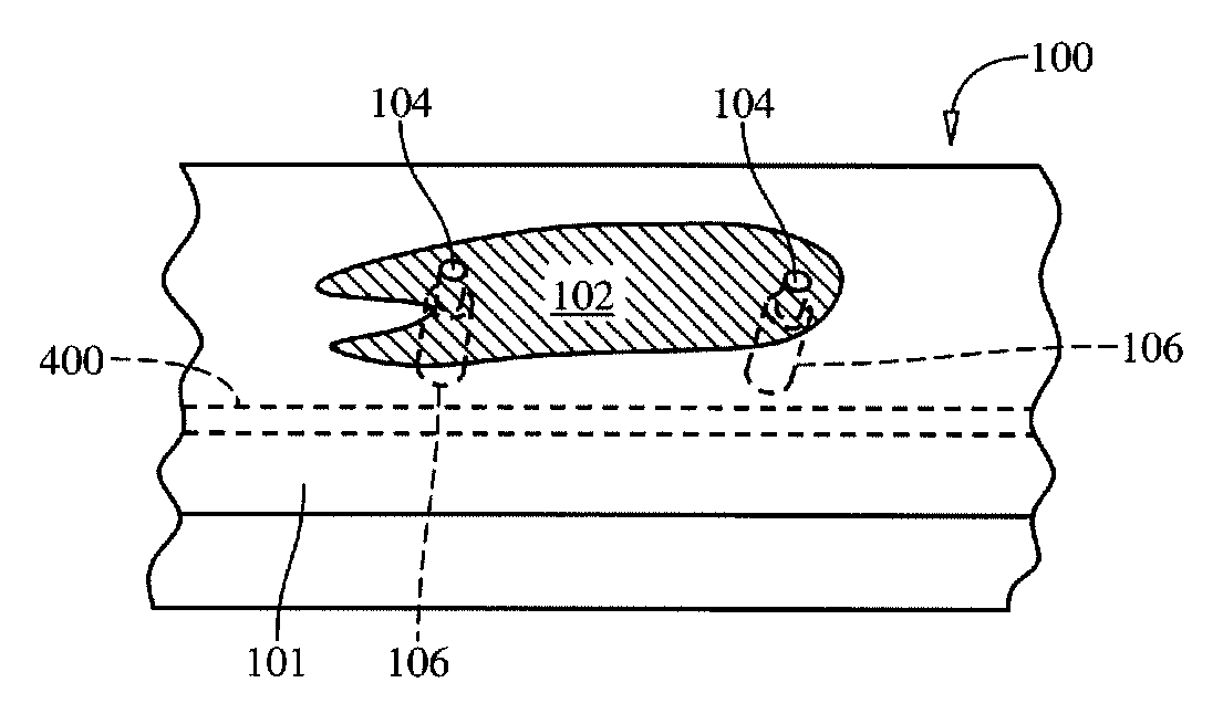
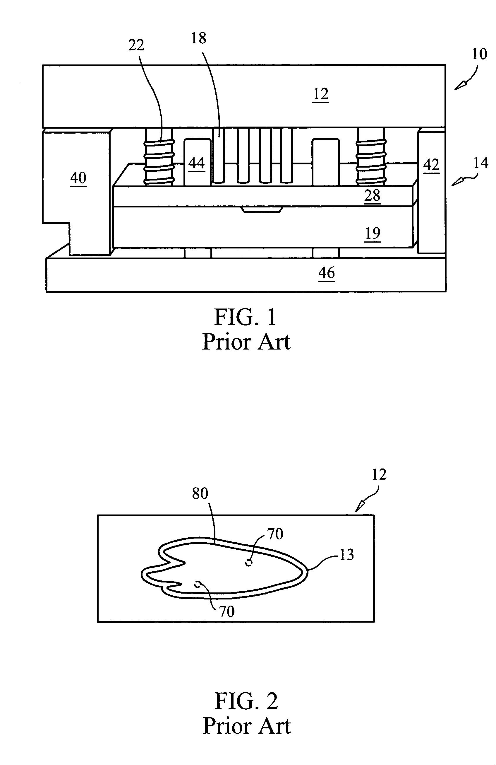
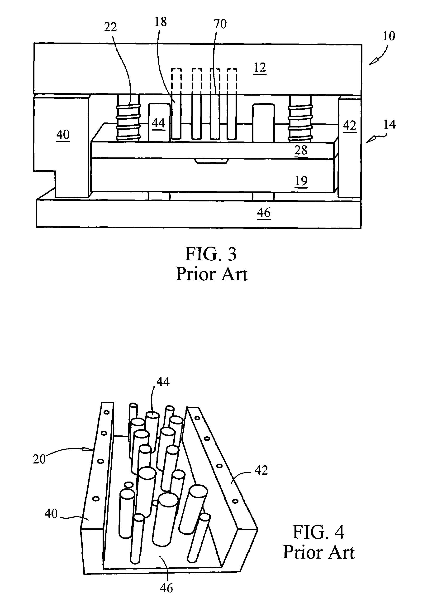
[0027]Referring now to FIGS. 1-5, there is shown a tool assembly 10 which is generally made in accordance with the prior art, but which may be used in a new or novel manner. Particularly, the tool assembly 10 includes a tool 12 which may be made according to the teachings of The '742 patent or which may be made according to such undesirable tool formation strategies as being cut or formed from a substantially solid block of material (i.e., by traditional tool formation strategies or techniques). As will be apparent from reading this description, even the traditional tool assembly 10 may be utilized in a new and novel manner to overcome some of the above-noted drawbacks, even if the tool assembly 10 is not modified or replaced in accordance with the teachings of the preferred embodiment of the invention. Moreover, the tool 12 is meant to generally refer to substantially any desired tool and is not limited to a particular type of tool, and includes an object forming surface 13 which i...


PUM

PropertyMeasurementUnit
massaaaaaaaaaa
sizeaaaaaaaaaa
soft modelaaaaaaaaaa

Abstract

A tool 100 having a forming surface 102 being formed from a contiguous material 101 and including, within the contiguous material 101 into which the forming surface 102 is operatively resident, a cylinder 150, 170 or other selectively movable member which may be selectively used to remove an object from the tool 100.

Description

FIELD OF THE INVENTION[0001]The present invention generally relates to a tool having an ejection assembly, a method for making such a tool, and a method for ejecting a formed object from the tool and more particularly, to a new and novel tool and tool formation strategy which allows a formed object to be quickly removed from the tool while substantially reducing the likelihood of damage to the object and which overcomes current deficiencies and drawbacks associated with current techniques and strategies.BACKGROUND OF THE INVENTION[0002]A tool is used to selectively form or create an object. It should be realized, at the outset, that the term “tool”, as used throughout this description, is meant to refer to any device, assembly, and / or tangible entity which is adapted to be selectively used to form or create substantially any sort of object and that nothing in this description is meant to (or should be construed as) limiting the tool to that which produces a certain object or a certa...

Claims


Application Information

Patent Timeline
Patent Type & Authority Patents(United States)
IPC IPC(8): A21C11/00
CPCB21D45/02B29C33/302B29C45/4005B29C33/442Y10T29/5184Y10T29/49826
Inventor MANUEL, MARK
Owner EDMOND DANTES HLDG LLC
Why Eureka
Try Eureka