Portable and inflatable antenna device

a technology of antenna device and portable body, which is applied in the direction of antenna, antenna details, antenna feed intermediates, etc., can solve the problems of inability to easily pack and deploy users, antennas that are not highly portable, and antennas that are expensiv

Inactive Publication Date: 2009-07-28
THE UNITED STATES OF AMERICA AS REPRESENTED BY THE SECRETARY OF THE NAVY
View PDF4 Cites 16 Cited by
  • Summary
  • Abstract
  • Description
  • Claims
  • Application Information

AI Technical Summary

Problems solved by technology

However, current antennas are not highly portable, as they are often heavy, bulky, and comprised of rigid materials.
Such antennas tend to be costly and cannot easily be packed and deployed by a user due to the use of rigid structures within the antenna.

Method used


Image

  • Portable and inflatable antenna device
  • Portable and inflatable antenna device
  • Portable and inflatable antenna device

Examples


Embodiment Construction

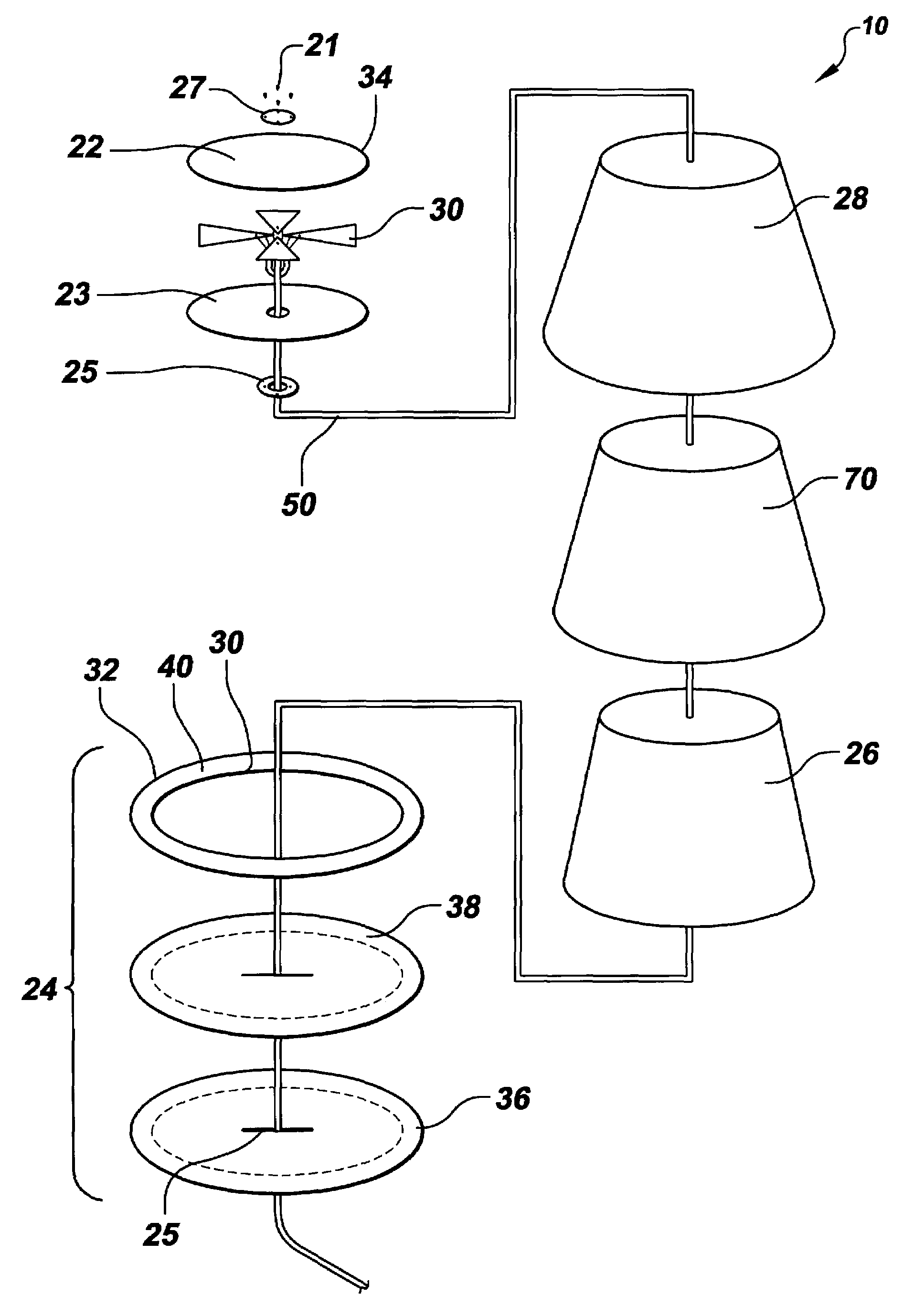
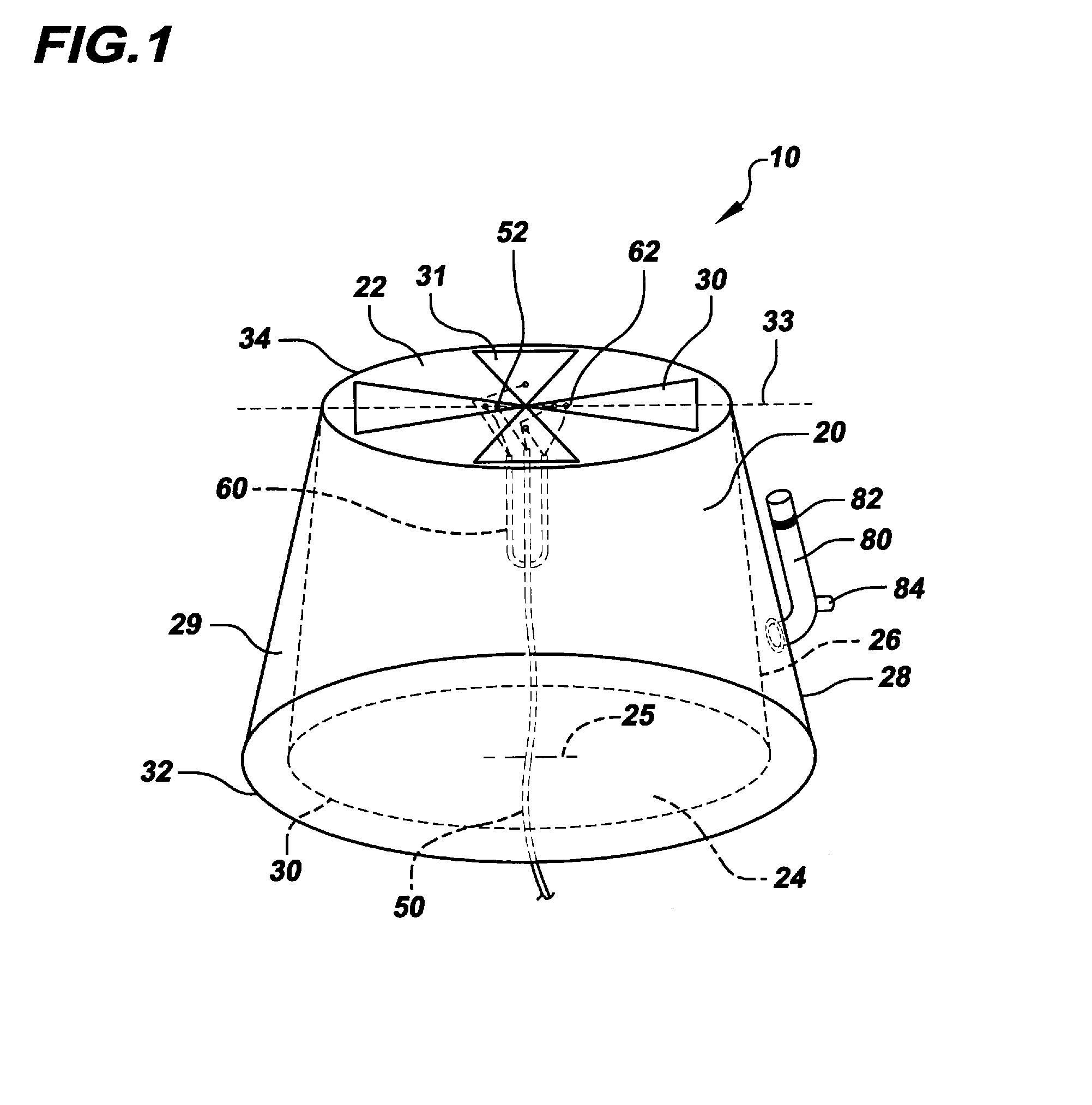
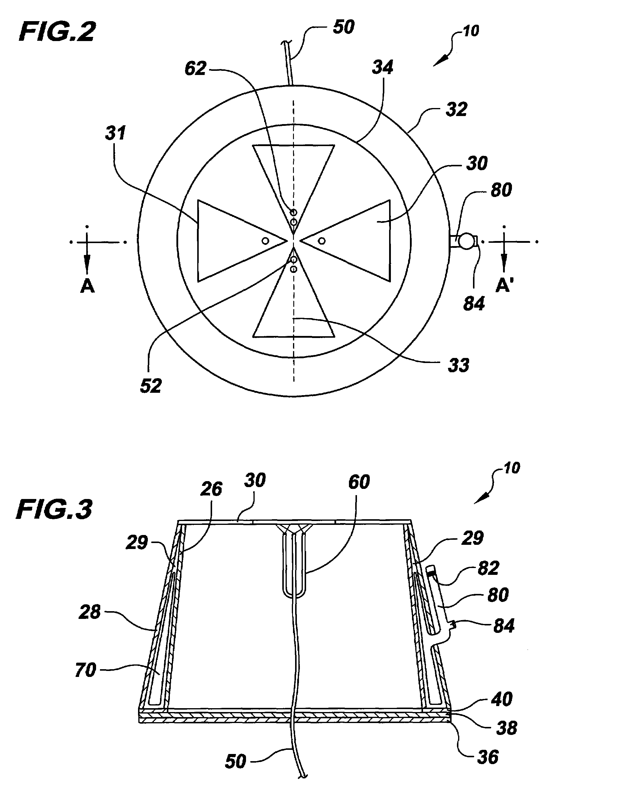
[0013]Referring to FIGS. 1-5, there is shown an embodiment of the portable and inflatable antenna device 10. Antenna 10 may include a support structure 20, a flexible antenna element 30, a feed line 50, a phase line 60, an inflatable bladder 70 (see FIG. 3), and an inflation apparatus 80. Antenna 10 may be configured to operate in various frequency bands. As an example, antenna 10 may be configured to operate in the ultra-high frequency satellite communications (UHFSATCOM) band and may have an approximate gain of 5 dBi over such band. Antenna 10 may be configured to have various polarizations, such as right-hand circular, left-hand circular, vertical, or horizontal.

[0014]Support structure 20 may be comprised of a flexible material, such as nylon. In some embodiments, support structure 20 may be substantially cylindrical in shape. As an example, support structure 20 may have a diameter of 40 cm and a height of 24 cm. In some embodiments, support structure 20 may comprise a circular t...


PUM


Abstract

An inflatable antenna may include a support structure comprised of a flexible material, the support structure having an inner wall and an outer wall, the inner wall and the outer wall defining an inflation region; a flexible antenna element contained within the support structure; a feed line and a phase line connected to the flexible antenna element; an inflatable bladder contained within the inflation region; and an inflation apparatus coupled to the support structure and in fluid communication with the inflatable bladder. In some embodiments, the inflatable bladder may be readily inserted and removed from the support structure through an opening within the support structure. The inflatable antenna may operate in the UHF satellite communications band. The feed line and phase line may be perpendicularly oriented with respect to the flexible antenna element. In some embodiments, the support structure may not include an inner wall.

Description

FEDERALLY-SPONSORED RESEARCH AND DEVELOPMENT[0001]The Portable and Inflatable Antenna Device was developed with Federal funds and is assigned to the United States Government. Licensing and technical inquiries may be directed to the Office of Patent Counsel, Space and Naval Warfare Systems Center, San Diego, Code 360012, San Diego, Calif., 92152; telephone (619) 553-3001, facsimile (619) 553-3821. Reference Navy Case No. 98664.BACKGROUND OF THE INVENTION[0002]Communication via ultra-high frequency satellite systems (UHF SATCOM) and mobile user objective systems (MUOS) has become more portable due to the development of portable radios that support such waveforms. To fully utilize such portable systems, corresponding antennas must also be portable. However, current antennas are not highly portable, as they are often heavy, bulky, and comprised of rigid materials. Such antennas tend to be costly and cannot easily be packed and deployed by a user due to the use of rigid structures within...

Claims


Application Information

Patent Timeline
Patent Type & Authority Patents(United States)
IPC IPC(8): H01Q1/08H01Q15/20
CPCH01Q1/081H01Q21/24H01Q9/28
Inventor ALL, CHRISTOPHER D.BARNETT, JAMIN E.TAYLOR, ROBERT A.
Owner THE UNITED STATES OF AMERICA AS REPRESENTED BY THE SECRETARY OF THE NAVY
Why Eureka
Try Eureka