Coupler for interconnecting electrical connectors

a technology of electrical connectors and couplings, applied in the direction of coupling device connections, coupling protective earth/shielding arrangements, electric discharge lamps, etc., can solve the problem of inherently susceptible to crosstalk

Active Publication Date: 2009-08-11
BISON PATENT LICENSING LLC
View PDF36 Cites 46 Cited by
  • Summary
  • Abstract
  • Description
  • Claims
  • Application Information

AI Technical Summary

Benefits of technology

[0008]Optionally, the first mating interface is configured for mating with a quad-type of mating connector representing a data communication plug, and the second mating interface is configured for mating with a standard RJ-45 type of mating connector representing a RJ-45 plug. The contact sub-assembly includes a circuit board and a plurality of second contacts terminated to the circuit board, wherein the second contacts are presented at the second mating interface, and the first contacts are terminated to the circuit board and electrically connected with corresponding second contacts by the circuit board. Optionally, the contact sub-assembly may include a circuit board, wherein the contact modules extend from a first surface of the circuit board and a tray extends from a second surface of the circuit board. Pairs of the first contacts are held by the contact modules and the second contacts are held by the tray.

Problems solved by technology

The RJ-45 plug design is dictated by industry standards and is inherently susceptible to crosstalk.

Method used


Image

  • Coupler for interconnecting electrical connectors
  • Coupler for interconnecting electrical connectors
  • Coupler for interconnecting electrical connectors

Examples


Embodiment Construction

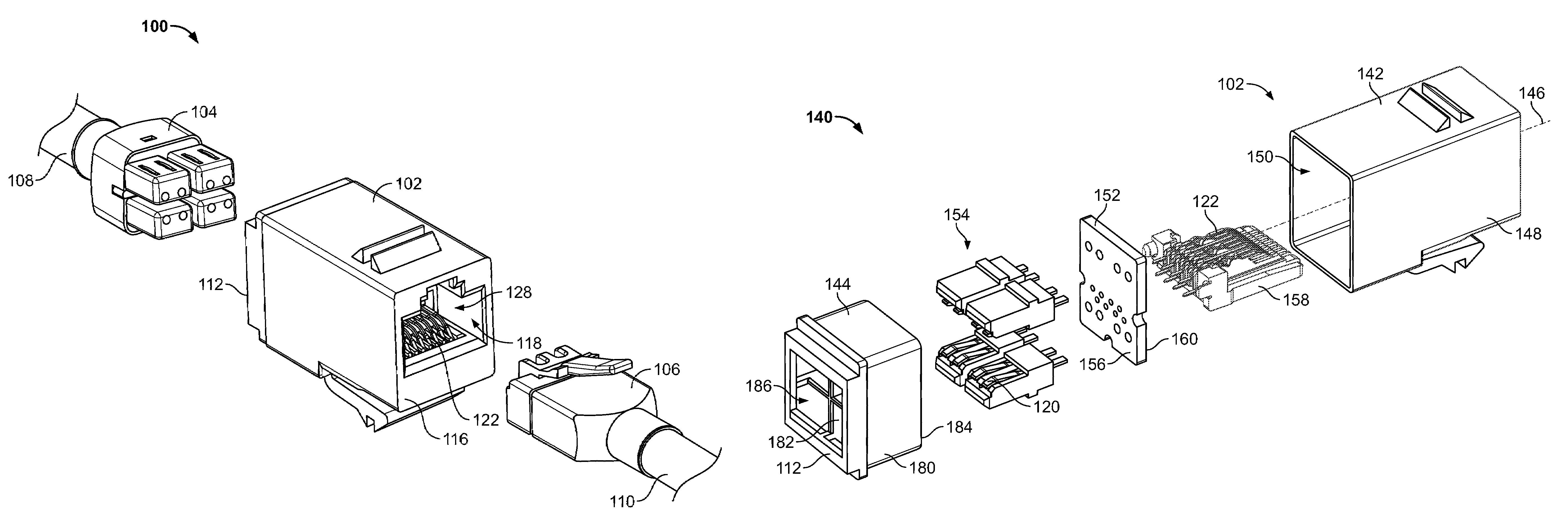
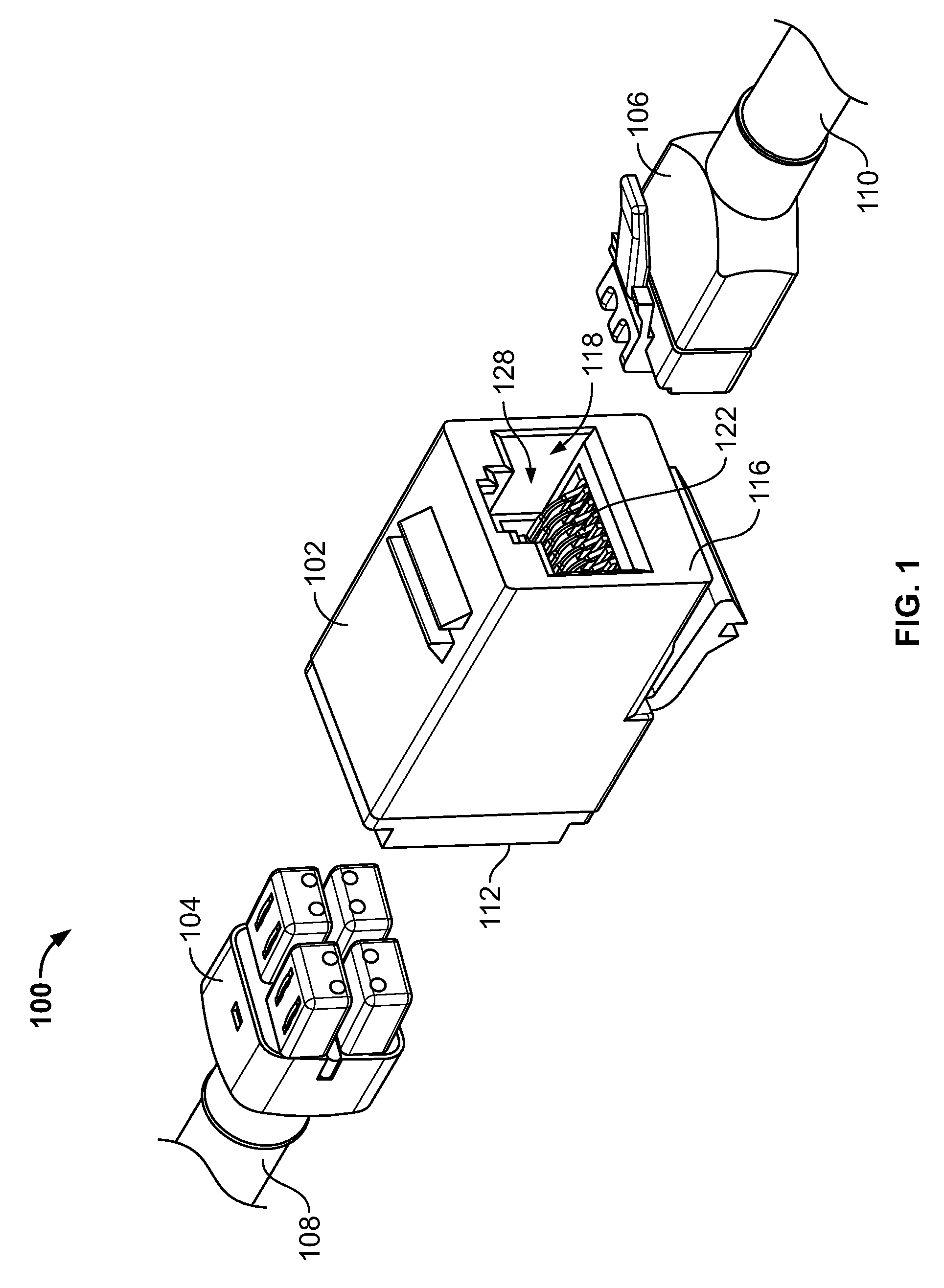
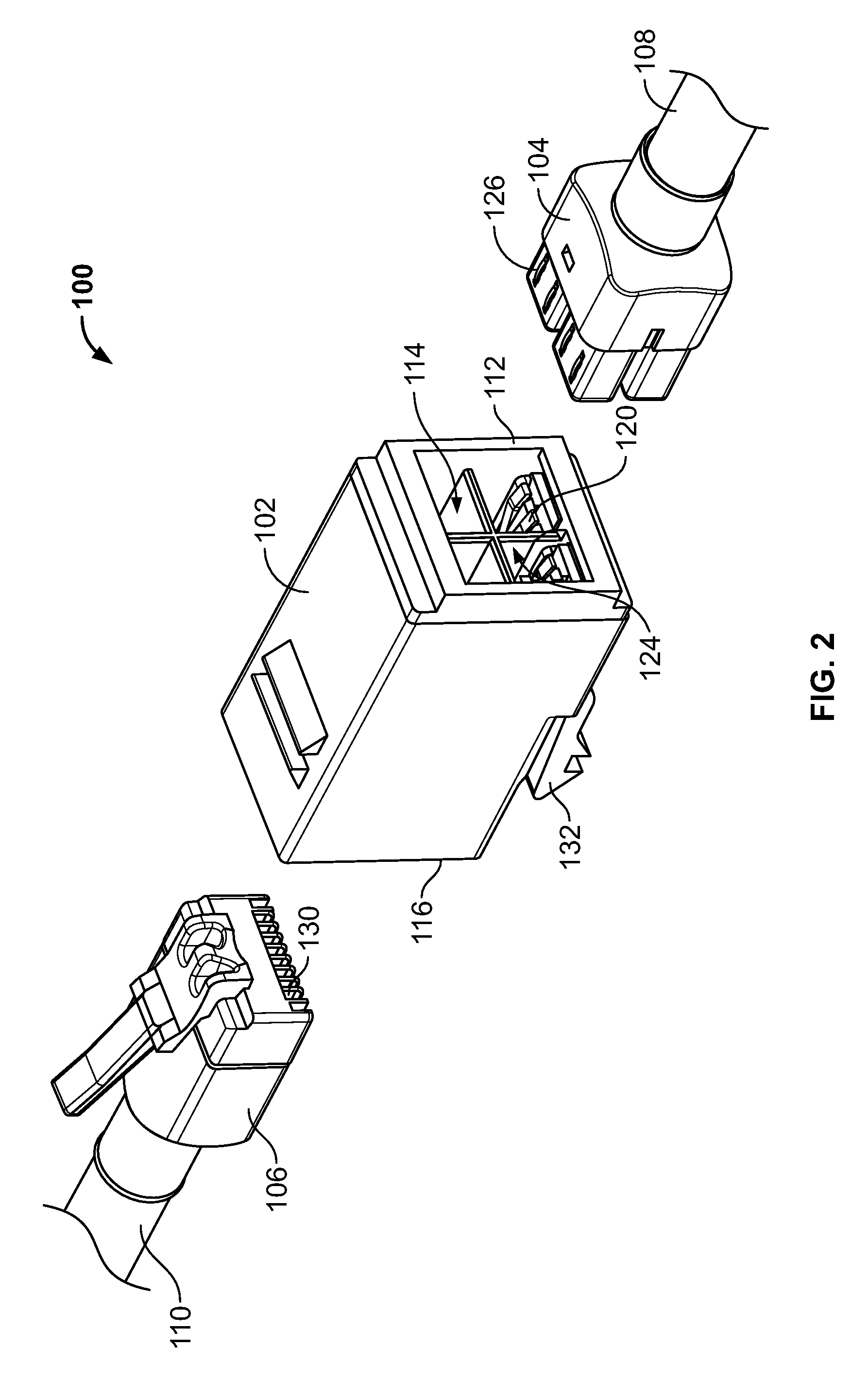
[0027]FIG. 1 is a front perspective view of a connector assembly 100 in an unassembled state including a coupler 102 for interconnecting first and second mating connectors 104, 106. FIG. 2 is a rear perspective view of the connector assembly 100. In an exemplary embodiment, the mating connectors 104, 106 define plug-type communication connectors each having four pairs of conductors defining different signal paths. Optionally, the first mating connector 104 may define a quad-type plug having contacts arranged in quadrants, such as the quad-type plug described in commonly owned U.S. patent application Ser. No. 11 / 707,612, titled “Electrical Connector with Enhanced Jack Interface”, the disclosure and subject matter of which is herein incorporated by reference in its entirety. The second mating connector 106 may be a standard RJ-45 plug connector. Optionally, the first and second mating connectors 104, 106 may both be quad-type plugs. While the connector assembly 100 is described in ter...


PUM


Abstract

A coupler includes a coupler body having a first mating end defining a first mating interface configured for mating with a first mating connector and a second mating end defining a second mating interface configured for mating with a second mating connector. A contact sub-assembly is received within the coupler body, wherein the contact sub-assembly has first contacts grouped in differential pairs and presented at the first mating end and second contacts grouped in differential pairs and presented at the second mating end. At least one shielding member is located within the coupler body, wherein the at least one shielding member isolates each differential pair of first contacts from an adjacent differential pair of the first contacts.

Description

BACKGROUND OF THE INVENTION[0001]The subject matter herein relates generally to connector assemblies, and more particularly, to a coupler for interconnecting electrical connectors.[0002]In electrical systems, there is increasing concern for preserving signal integrity as signal speed and bandwidth increase. The degree of signal degradation, or amplitude of crosstalk, generally increases as the frequency increases.[0003]For example, a typical industry standard type RJ-45 communication connector includes four pairs of conductors defining different signal paths. The RJ-45 plug design is dictated by industry standards and is inherently susceptible to crosstalk. Additional crosstalk can be created by the contacts in the jack that interface with the contacts in the plug.[0004]Due to the problems that are inherent in connectors such as the RJ-45 jacks, alternative jacks having enhanced interfaces have been developed to enhance performance. For example, Tyco Electronics Corporation describe...

Claims


Application Information

Patent Timeline
Patent Type & Authority Patents(United States)
IPC IPC(8): H01R13/648
CPCH01R13/514H01R13/65807H01R31/005H01R13/6589H01R31/06H01R13/6592H01R24/64H01R13/6582
Inventor PEPE, PAUL JOHNHOWER, JAMES SHANNON
Owner BISON PATENT LICENSING LLC
Why Eureka
Try Eureka