Mechanical delay mechanisms for inertial igniters for thermal batteries and the like

a technology of mechanical delay mechanism and thermal battery, which is applied in the direction of impact fuze, ammunition fuze, weapons components, etc., can solve the problems of inability to store for long periods of time, and inability to use relatively small thermal batteries

Active Publication Date: 2009-09-15
OMNITEK PARTNERS LLC
View PDF18 Cites 12 Cited by
  • Summary
  • Abstract
  • Description
  • Claims
  • Application Information

AI Technical Summary

Problems solved by technology

The aforementioned currently available inertial igniters have a number of shortcomings for use in thermal batteries, specifically, they are not useful for relatively small thermal batteries for munitions with the aim of occupying relatively small volumes, i.e., to achieve relatively small height total igniter compartment height 13 (FIG. 1).
In addition, since the pyrotechnic materials of the currently available igniters 20 are not sealed inside the igniter, they are prone to damage by the elements and cannot usually be stored for long periods of time before assembly into the thermal batteries unless they are stored in a controlled environment.

Method used


Image

  • Mechanical delay mechanisms for inertial igniters for thermal batteries and the like
  • Mechanical delay mechanisms for inertial igniters for thermal batteries and the like
  • Mechanical delay mechanisms for inertial igniters for thermal batteries and the like

Examples


Embodiment Construction

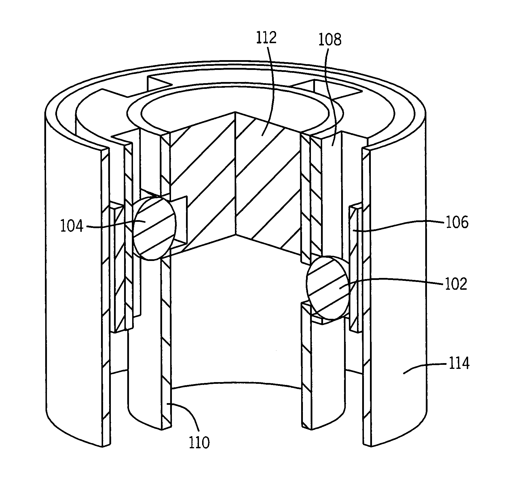
[0024]FIGS. 4a-4c illustrate an embodiment of an inertia igniter 100 of the present invention. Given that a certain total stroke is necessary to achieve the desired fire / no-fire characteristics, the design can be implemented with very long total safety delay stroke, i.e., a very long delay time, since the total stroke is being distributed among multiple setback safety delay stages. Such an implementation would allow for reducing the overall axial length of the miniature inertial igniter. Alternately, this multi-stage design concept can be implemented to provide enhanced fire / no-fire characteristics which, if implemented in a single-stage design, would render the device impractically long in the axial direction.

[0025]The schematic of such a two stage safety delay design is shown in FIGS. 4a-4c. The inertia igniter, shown in FIG. 4a at rest, has primary and secondary locking balls 102, 104, primary and secondary setback collars 106, 108, a main body 110 and striker 112 all housed in a...


PUM


Abstract

An inertia igniter including: a housing; and a movable striker supported by first and second stages, the first stage having a first locking element for releasing the second stage upon a first predetermined acceleration of the housing and the second stage having a second locking element for releasing the striker upon a second predetermined acceleration of the housing greater than the first predetermined acceleration. Wherein the first and second locking elements of the first and second stages occupy a common cross-sectional volume along a longitudinal axis of the housing.

Description

CROSS-REFERENCE TO RELATED APPLICATIONS[0001]The present application claims priority to U.S. provisional patent application Ser. No. 60 / 835,023, filed on Aug. 2, 2006, the entire contents of which is incorporated herein by reference.GOVERNMENT RIGHTS[0002]This invention was at least partially made with Government support under Contract No. W15QKN-07-C-0042, awarded by the U.S. Army. The Government may have certain rights in this invention.BACKGROUND OF THE INVENTION[0003]1. Field of the Invention[0004]The present invention relates generally to mechanical acceleration delay mechanisms, and more particularly for inertial igniters for thermal batteries used in gun-fired munitions and other similar applications.[0005]2. Prior Art[0006]Thermal batteries represent a class of reserve batteries that operate at high temperatures. Unlike liquid reserve batteries, in thermal batteries the electrolyte is already in the cells and therefore does not require a distribution mechanism such as spinni...

Claims


Application Information

Patent Timeline
Patent Type & Authority Patents(United States)
IPC IPC(8): F42C15/24
CPCF42C1/04F42C15/24F42C11/008
Inventor RASTEGAR, JAHANGIR S.MURRAY, RICHARDSPINELLI, THOMAS
Owner OMNITEK PARTNERS LLC
Why Eureka
Try Eureka