Systems and methods for controlling a ramp rate of a wind farm

a technology of wind farm and ramp rate, which is applied in the direction of electric generator control, process and machine control, instruments, etc., can solve the problems of inability to easily control the rate of power change of thermal power generators and the difficulty of instantaneous power output change of thermal power plants

Active Publication Date: 2009-11-03
GE INFRASTRUCTURE TECH INT LLC
View PDF14 Cites 47 Cited by
  • Summary
  • Abstract
  • Description
  • Claims
  • Application Information

AI Technical Summary

Problems solved by technology

However, it is often difficult to change power output of thermal power plants instantaneously.
Accordingly, rate of change of power used by the thermal power generators cannot be easily controlled.

Method used


Image

  • Systems and methods for controlling a ramp rate of a wind farm
  • Systems and methods for controlling a ramp rate of a wind farm
  • Systems and methods for controlling a ramp rate of a wind farm

Examples


Embodiment Construction

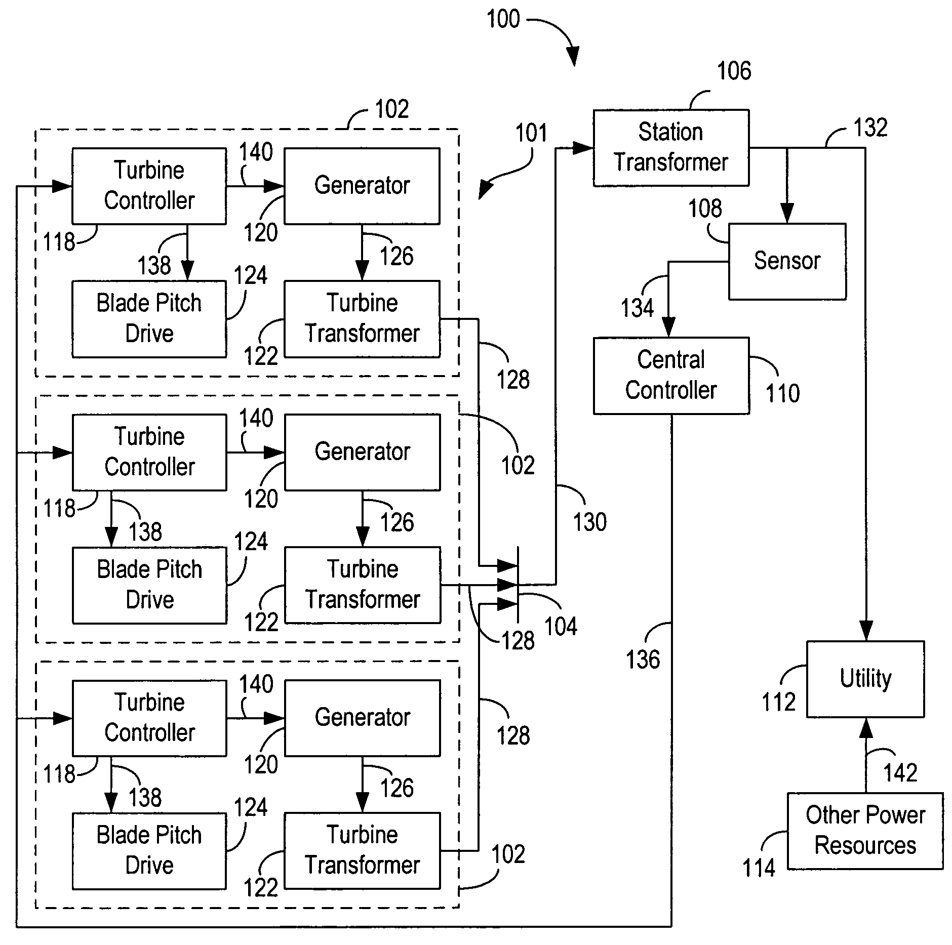
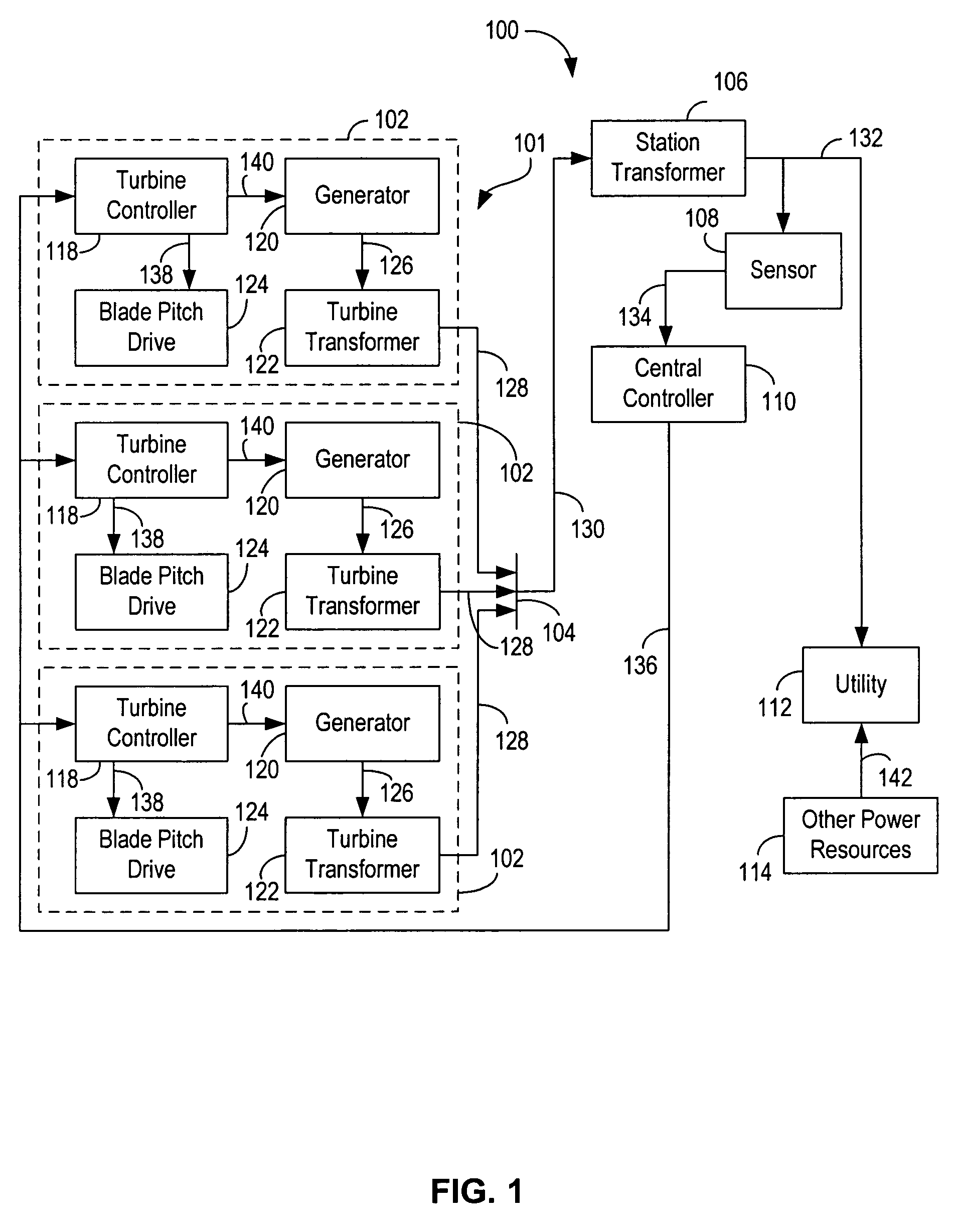
[0013]FIG. 1 is a block diagram of an embodiment of a system 100 for controlling a ramp rate of a wind farm. System 100 includes a wind farm 101 that includes a plurality of wind turbines 102. System 100 further includes a feeder 104, a station transformer 106, a sensor 108, a central controller 110, a utility 112, and power sources 114 other than wind turbines 102. Each wind turbine 102 includes a turbine controller 118, a generator 120, a turbine transformer 122, and a variable blade pitch drive 124. As used herein, the term controller is not limited to just those integrated circuits referred to in the art as a controller, but broadly refers to a processor, a microcontroller, a microcomputer, a programmable logic controller, an application specific integrated circuit, and any other programmable circuit. Examples of power resources 114 include a thermal station, a hydroelectric station, and a nuclear power station. Examples of the thermal station include a coal-fired station and a ...


PUM


Abstract

A method for controlling a ramp rate of a wind farm is described. The method includes predicting an initial predicted power to be output by a wind farm including a wind turbine.

Description

BACKGROUND OF THE INVENTION[0001]The invention relates generally to wind power generation, and more particularly to systems and methods for controlling a ramp rate of a wind farm.[0002]A wind power generation system generally includes a wind farm having a plurality of wind turbine generators supplying power to a utility grid. Collective power output of the wind farm is greatly influenced by wind conditions on individual wind turbine generators. Utilities often have other power resources, such as thermal power plants to balance their electrical loads, thus accommodating variability in wind conditions during intermittent wind conditions. Thermal power plants may include, for example, coal and gas fired stations. Power fluctuation of wind farms due to gusty or low wind conditions is usually dealt with by adjusting power output of these thermal power plants to provide relatively constant overall power matching demands.[0003]However, it is often difficult to change power output of therma...

Claims


Application Information

Patent Timeline
Patent Type & Authority Patents(United States)
IPC IPC(8): G06F19/00G05D3/12
CPCF03D7/0284F03D7/048F05B2260/821Y02E10/725F05B2270/404Y02E10/723F05B2270/335Y02E10/72
Inventor CARDINAL, MARK EDWARDBRUGGER, REINHARDKIRCHNER, ANDREAS
Owner GE INFRASTRUCTURE TECH INT LLC
Why Eureka
Try Eureka