Driver for an OLED passive-matrix display

a technology of organic lightemitting diodes and drive shafts, applied in the field of drives, can solve the problems of reducing the uniformity of pixel-to-pixel luminance, limiting the life of lcds, and separating light sources, and achieve the effect of efficient power-up mode operation

Inactive Publication Date: 2009-11-17
STMICROELECTRONICS SRL
View PDF9 Cites 29 Cited by
  • Summary
  • Abstract
  • Description
  • Claims
  • Application Information

AI Technical Summary

Benefits of technology

[0011]In order to overcome the deficiencies of the prior art, an OLED passive-matrix display is disclosed that allows for an efficient power-up mode of operation, as well as the ability to adjust power (e.g., voltage and / or current) supplied to the OLEDs based on need during normal, steady-state conditions.
[0012]In one embodiment, the OLED passive-matrix display includes a monitor circuit that monitors the real-time voltage levels used by the OLEDs and a voltage adjusting circuit that changes the supply voltage in response to signals received from the monitor circuit. During a power-up mode, the voltage adjusting circuit uses a fixed reference voltage as a basis for generating supply voltage when the power needed by the OLEDs is not well defined. But after a predetermined period of time or in response to an external signal, the voltage adjusting circuit switches from reading the fixed reference voltage to reading a variable voltage level supplied from the monitor circuit. This variable voltage is based on voltage readings of the OLEDs, such as reading the voltage drops directly across the OLEDs. In response to this variable voltage level, the voltage adjusting circuit modifies the voltage supplied to the OLEDs. In this way, there is no wasted power dissipation and the circuit has real-time tracking of all the OLEDs.

Problems solved by technology

One drawback, however, to LCDs is that they require a separate light source, typically a fluorescent backlight, to illuminate the panel.
In fact, the LCD's brightness depends solely on its backlight and it is this backlight that limits the life of the LCD.
One problem with OLED displays is the variation of the current-voltage (I-V) characteristics over time, which causes degradation of the luminance efficiency and pixel-to-pixel luminance uniformity.
Such high currents cause excess voltage drops on the OLEDs that results in wasted power consumption.
However, this application only discloses indirectly measuring voltage and current used by the display pixels, which is less desirable.
Additionally, there is no well-defined technique disclosed for efficient power-up of the OLED display.
That is, when the display is first powered on, the pixels are off and the required voltage needed by the OLED display is not well defined.

Method used


Image

  • Driver for an OLED passive-matrix display
  • Driver for an OLED passive-matrix display
  • Driver for an OLED passive-matrix display

Examples


Embodiment Construction

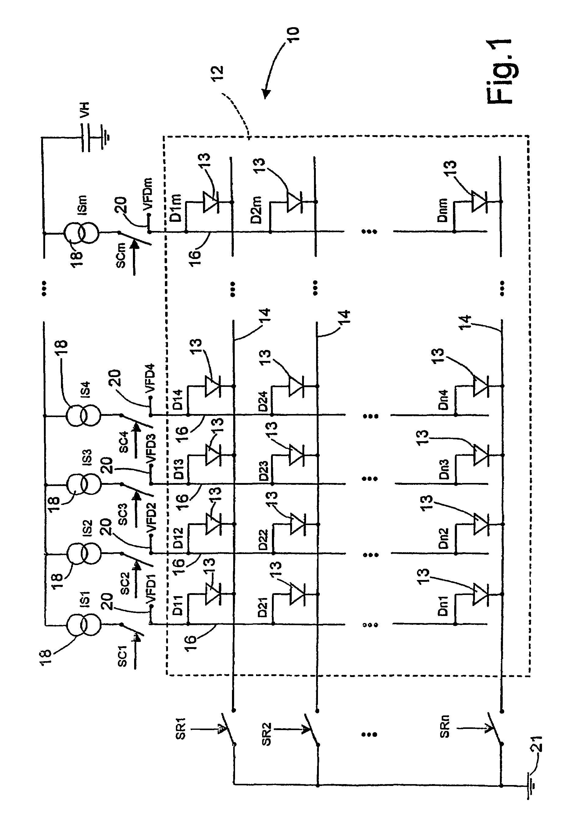
[0018]FIG. 1 shows a display portion 10 of an OLED passive-matrix display. A matrix 12 of OLEDs 13 includes parallel rows 14 of conductors positioned orthogonally to parallel columns 16 of conductors. Each row 14 includes OLED Dx1 to Dxm (where x is the row number and m is the number of columns), and each column 16 includes OLEDs D1x to Dnx (where n is the number of rows and x is the column number). Each column is biased with a current generator 18 (1 to m) coupled at its upstream end to a voltage source VH and at its downstream end to one of the column switches SC1-SCm. Each row 14 includes one of the row switches SR1-SRn with its upstream end coupled to the OLEDs, and its downstream end coupled to a cathode 21. Column switches SC1-SCm and row switches SR1-SRn are independently switchable so that each OLED can be selected individually irrespective of the other OLEDs. To measure voltage directly across the OLEDs, voltage taps 20 are coupled to the columns as indicated at VFD1-VFDm. ...


PUM


Abstract

An OLED (organic light-emitting diode) passive-matrix display includes a display portion and a driver portion. The display portion includes a matrix of OLEDs for displaying information. The driver portion includes a monitor circuit and a voltage adjusting circuit. The voltage adjusting circuit has a power-up portion that generates a supply voltage based on a reference voltage. In response to an indication to switch modes, the voltage adjusting circuit switches to an operational mode wherein the supply voltage is generated based on the maximum voltage drop read across the OLEDs.

Description

BACKGROUND OF THE INVENTION[0001]1. Field of the Invention[0002]The present invention relates to displays, and more particularly to a driver for an Organic Light-Emitting Diode (OLED) passive-matrix display.[0003]2. Description of the Related Art[0004]Liquid crystal displays (LCDs) are the most common type of flat-panel display used today. One drawback, however, to LCDs is that they require a separate light source, typically a fluorescent backlight, to illuminate the panel. In fact, the LCD's brightness depends solely on its backlight and it is this backlight that limits the life of the LCD.[0005]Because of these drawbacks, OLED displays are gaining in popularity. OLED displays are self-luminous and, therefore, do not require a separate backlight. Passive-matrix OLED displays have a simple structure and are well suited for low-cost and low-information-content applications, such as alphanumeric displays. Active-matrix OLEDs have an integrated electronic backplane that enables high-re...

Claims


Application Information

Patent Timeline
Patent Type & Authority Patents(United States)
IPC IPC(8): G09G3/32G09G3/18G09G3/38G09G3/22
CPCG09G3/3216G09G3/22G09G3/3283G09G2330/028G09G2320/041G09G2320/043G09G2330/021G09G2320/029
Inventor PULVIRENTI, FRANCESCOBONTEMPO, GREGORIOMASAKI, MURAKATAAKINORI, HAYAFUJI
Owner STMICROELECTRONICS SRL
Why Eureka
Try Eureka