Supercharge Your Innovation With Domain-Expert AI Agents!

Operator assist device for vehicular air brake actuation

a technology of assist device and brake, which is applied in the direction of mechanical control device, process and machine control, instruments, etc., can solve the problems of the size of service vehicles such as large trucks and semi-tractors. , to achieve the effect of reducing repetitive stress injuries to the hands and wrists of operators

Inactive Publication Date: 2009-12-08
DOAN CURTIS MICHAEL
View PDF29 Cites 0 Cited by
  • Summary
  • Abstract
  • Description
  • Claims
  • Application Information

AI Technical Summary

Benefits of technology

The mechanical assist device significantly reduces operator fatigue and repetitive stress injuries by allowing for easier and less strenuous operation of pneumatic control valves, minimizing the need for repetitive pulling motions and enhancing operational efficiency.

Problems solved by technology

Service vehicles, such as large trucks and semi-tractors trailers are typically quite massive, especially when laden, and thus are typically equipped with pneumatic brake systems.
As significant, non-trivial amounts of force are required to actuate the valves and the valves must be frequently actuated and deactuated during the course of operation of the vehicle, routine operation of the vehicle can cause repetitive stress injuries to the operators' hands and wrists.

Method used


Image

  • Operator assist device for vehicular air brake actuation
  • Operator assist device for vehicular air brake actuation
  • Operator assist device for vehicular air brake actuation

Examples


first embodiment

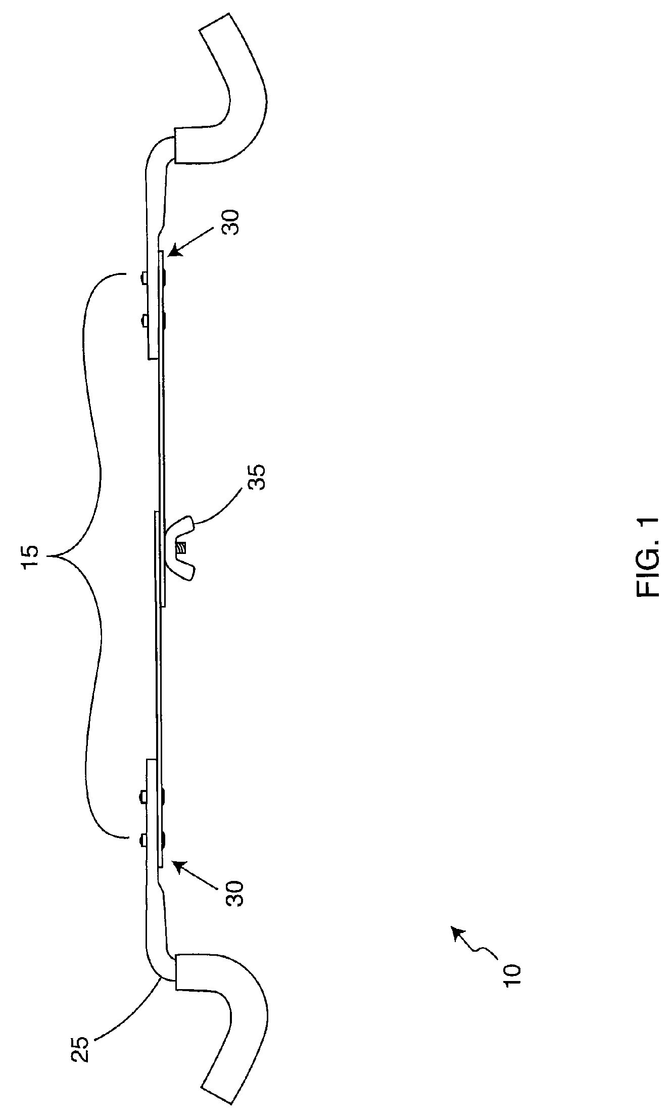
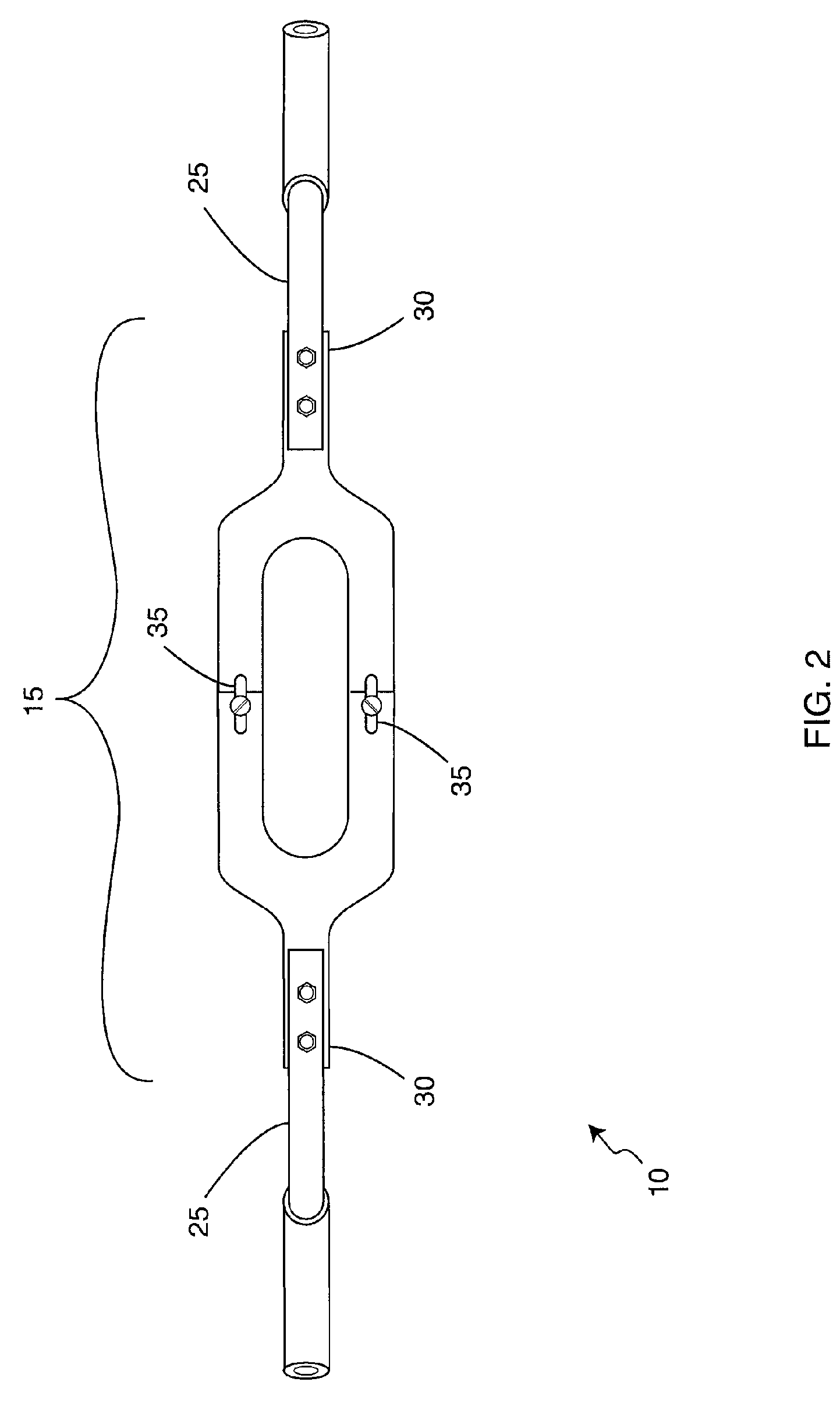
[0015]FIGS. 1-3 illustrate the present invention, a valve actuation assist or spring harness device 10 including a generally flat elongated oval portion 15 adapted to extend around one or more (typically two) push-pull type valve actuators 20 and angled lever-arm portions 25 extending from either end 30 of the elongated oval portion 15. The elongated oval portion 15 is typically of variable size to allow for engagement with valve actuators 20 positioned different distances apart. In one embodiment, the device 10 is constructed from two substantially identical halves fastened together by a pair of tightenable fastener members 35 (such as wingnut / bolt pairs) engaged through apertures 45 formed through the oval portion 15. In this embodiment, the aperture 45 through one half portion 40 is slotted to allow the size of the oval portion 15 to vary.

[0016]When the device 10 is operationally deployed around the one or more valve actuators 20, an operator may push down on one or both lever ar...

second embodiment

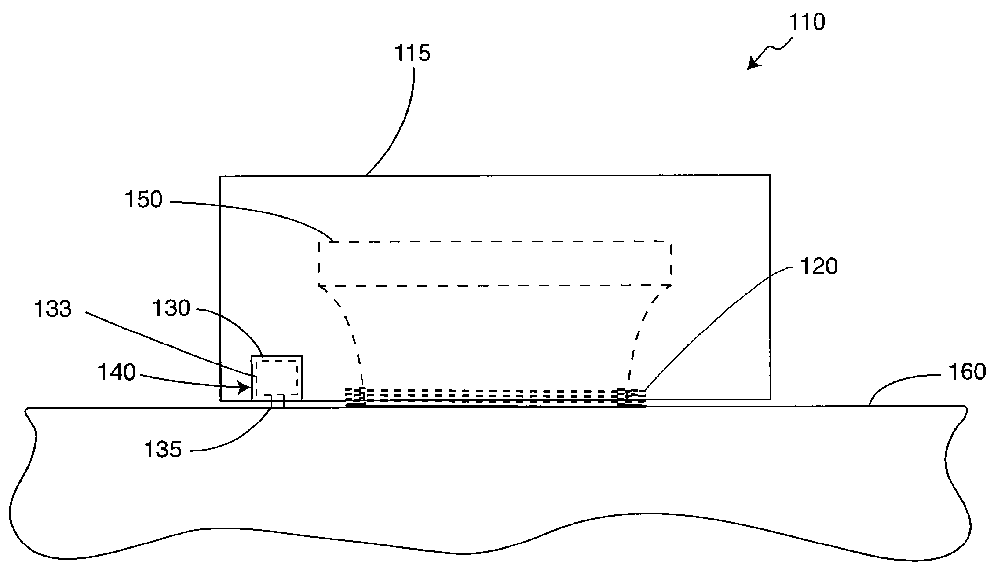
[0019]FIGS. 4-7C illustrate the present invention, valve actuation assist device 110 having a valve actuator engaging or cap portion 115 and a biasing portion 120 connected thereto and extending therefrom. The cap portion 115 further includes an inner cavity 125 sized to receive a valve actuator 150 and a generally flat bottom lip portion 128 defining the cavity opening. The valve actuator 150 extends form a vehicular dash 160 and is movable between a first, actuated position and a second, deactuated position. In the first, actuated position the valve actuator is pushed in closer to the dash 160 while in the second, deactuated position the valve actuator 150 is positioned relatively remote from the dash 160.

[0020]The lip portion 128 includes a slotted aperture 129 formed therethrough. An engagement member 130 is fastened to a vehicle dash 160 adjacent to the valve actuator 150 desired to be engaged by the device 110 and positioned to intersect the slotted aperture 129. The slotted a...


PUM


Abstract

A mechanical assist assembly for translating a pushing motion from a vehicle operator into an oppositely directed valve deactuation force including a spring cap having a generally round cap portion, a locking recess formed in the cap portion, a helical compression spring operationally connected and extending from the cap portion and a locking bolt extending from a vehicle dash plate. The cap portion may be depressed to actuate the valve actuator, thereby increasing the potential energy of the compression spring. The cap may be rotated a first direction to engage the locking bolt and, once engaged, may be rotated a second direction to disengage the locking bolt. Disengaging the cap portion from the locking bolt enables the helical compression spring to release its stored potential energy and urge the valve actuator into its disengaged position.

Description

TECHNICAL FIELD OF THE INVENTION[0001]This invention relates to an operator assist device for vehicular air brake actuation and, more particularly, to a mechanical assist device for aiding a driver or vehicle operator in repeatedly actuating pneumatic control valves.BACKGROUND OF THE INVENTION[0002]Service vehicles, such as large trucks and semi-tractors trailers are typically quite massive, especially when laden, and thus are typically equipped with pneumatic brake systems. These brake systems typically have one or more brake valves located in the cab, which the driver may actuate and deactuate to control the brake system. The control valves are typically actuated by pulling a grippable portion of the valve head them towards the operator and are likewise deactuated by pushing the grippable portion in a reverse direction away from the operator. As significant, non-trivial amounts of force are required to actuate the valves and the valves must be frequently actuated and deactuated du...

Claims


Application Information

Patent Timeline
Patent Type & Authority Patents(United States)
IPC IPC(8): F16K35/00
CPCB60T15/04G05G1/02B60T17/04
Inventor DOAN, CURTIS MICHAEL
Owner DOAN CURTIS MICHAEL
Features
  • R&D
  • Intellectual Property
  • Life Sciences
  • Materials
  • Tech Scout
  • Unparalleled Data Quality
  • Higher Quality Content
  • 60% Fewer Hallucinations
Learn More