Lower extremity enhancer

Active Publication Date: 2009-12-08
RGT UNIV OF CALIFORNIA
View PDF27 Cites 244 Cited by
  • Summary
  • Abstract
  • Description
  • Claims
  • Application Information

AI Technical Summary

Problems solved by technology

In general, these attempts relied on an interpretation of muscle activity to prescribe a motion to the joints of the exoske

Method used


Image

  • Lower extremity enhancer
  • Lower extremity enhancer
  • Lower extremity enhancer

Examples


Embodiment Construction

[0031]The following description sets forth numerous specific configurations, parameters, and the like. It should be recognized, however, that such description is not intended as a limitation on the scope of the present invention, but is instead provided as a description of exemplary embodiments.

[0032]1. Overview

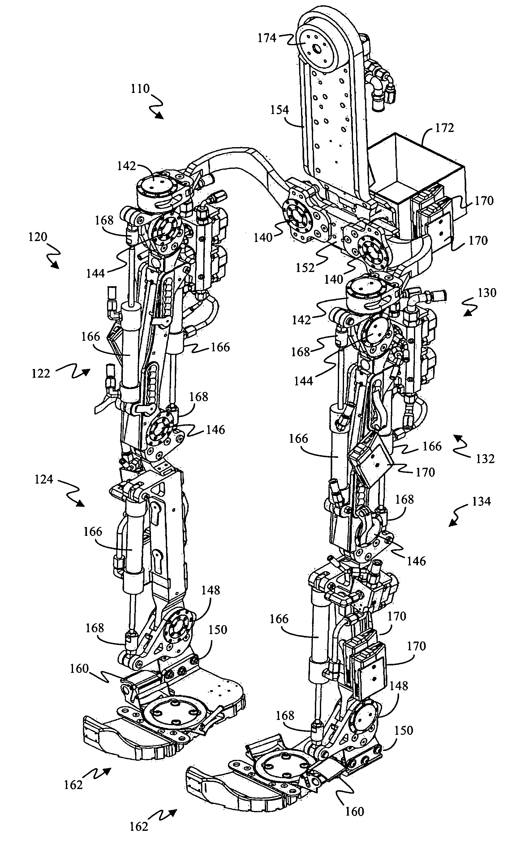
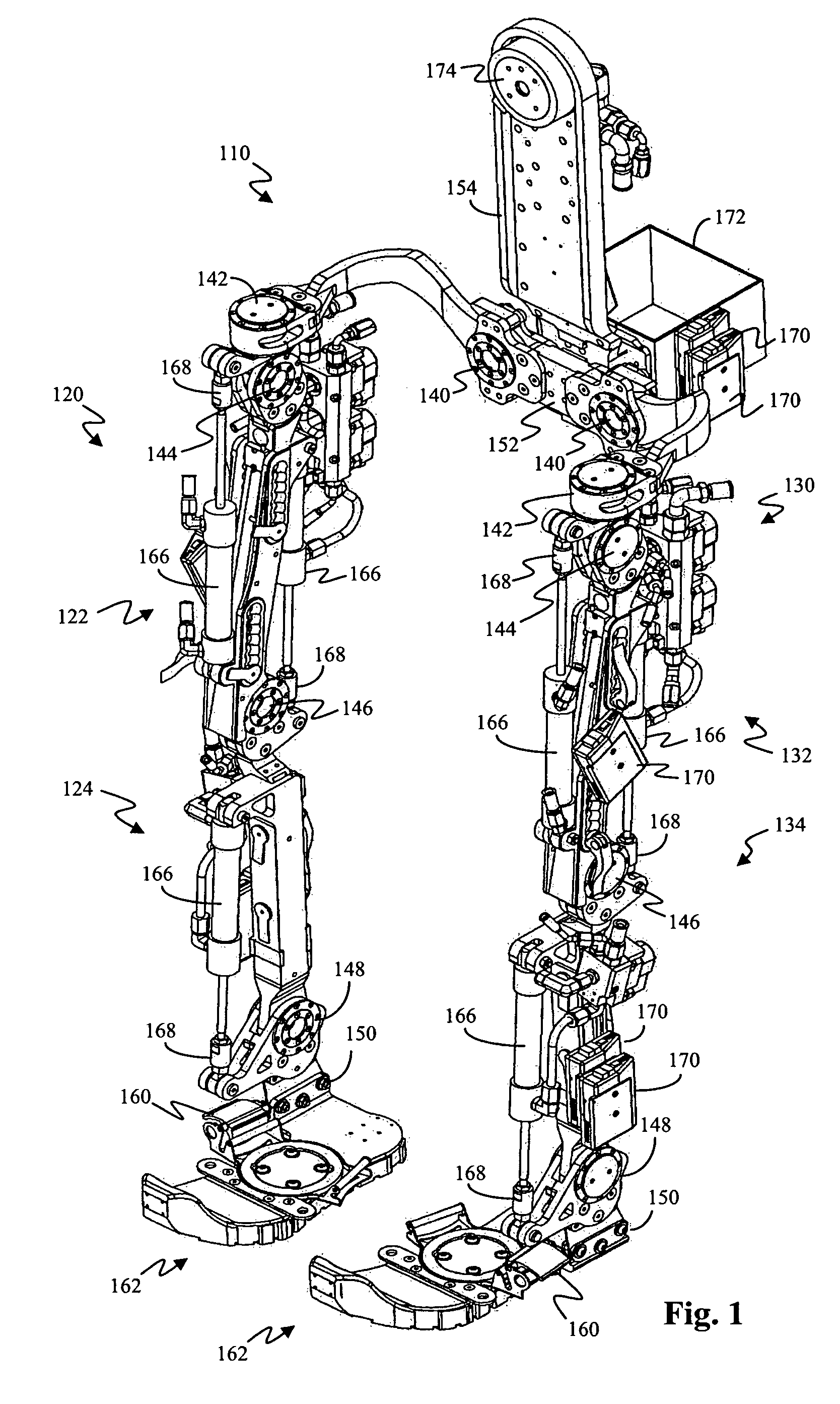
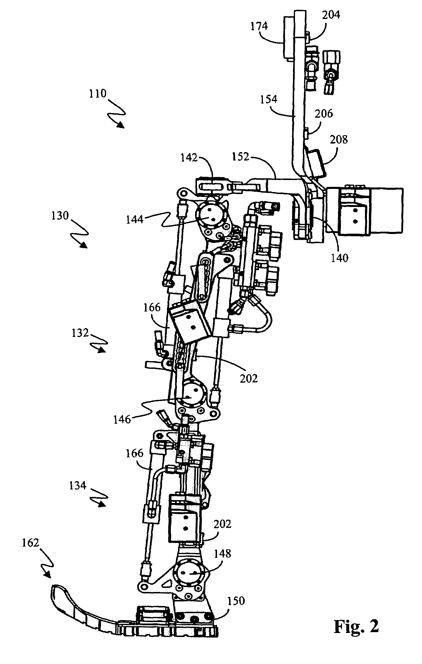
[0033]With reference to FIG. 1, in one exemplary embodiment, a lower extremity enhancer (hereinafter referred to as an “enhancer”) 110 is adapted to be worn by a user to enable the user to carry a load. In the present exemplary embodiment, enhancer 110 includes two leg supports 120, 130 (right leg support 120 and left leg support 130) having multiple jointed links 122, 124, 132, and 134. A back frame 154, which carries the load, is connected to proximal ends of leg supports 120, 130. Two foot links 162 are connected to distal ends of leg supports 120, 130. Actuators 166 are adapted to apply torque to leg supports 120, 130.

[0034]Enhancer 110 includes multiple articulating join...


PUM


Abstract

A lower extremity enhancer to be worn by a user to enable the user to carry a load includes two leg supports having a plurality of jointed links. Proximal ends of the leg supports are connected to a back frame adapted to carry the load. Distal ends of the leg supports are connected to two foot links. The leg supports are powered by a plurality of actuators adapted to apply torques to the leg supports in response to movement of the user's legs.

Description

CROSS-REFERENCE TO RELATED APPLICATIONS[0001]This application claims the benefit of U.S. Provisional Application No. 60 / 515,572, titled LOWER EXTREMITY ENHANCER, filed Oct. 29, 2003, the entire content of which is incorporated herein by reference.STATEMENT REGARDING FEDERALLY SPONSORED RESEARCH OR DEVELOPMENT[0002]This invention was made with government support under Contract No. DAAD19-01-1-0509 awarded by Defense Advanced Research Projects Agency (DARPA). The government has certain rights in the invention.BACKGROUND[0003]1. Field[0004]The present application relates to a robotic exoskeleton, and, more particularly, to a lower extremity enhancer to be worn by a user to enable the user to carry a load.[0005]2. Related Art[0006]A robotic exoskeleton to be worn by a user has been mostly the subject of science fiction. Attempts have been made to build a lower limb exoskeleton for both performance augmentation and rehabilitation purposes. In general, these attempts relied on an interpre...

Claims


Application Information

Patent Timeline
IPC IPC(8): A61F5/00
CPCA61F5/00A61H2201/165A61H3/008A61H1/0255A61H1/0266A61H3/00A61H2201/1215A61H2201/1246A61H2201/1676
Inventor KAZEROONI, HOMAYOONRACINE, JEAN-LOUISCHU, ANDREWZOSS, ADAM
Owner RGT UNIV OF CALIFORNIA
Why Eureka
Try Eureka