Apparatus and method for rejecting jammed coins

a technology of coin separator and rejector, which is applied in the direction of instruments, apparatus for dispensing discrete objects, record information storage, etc., can solve the problems of limiting the location where manufacturers of coin operated machines can place coin separators and rejectors

Inactive Publication Date: 2009-12-22
IMONEX SERVICES
View PDF213 Cites 8 Cited by
  • Summary
  • Abstract
  • Description
  • Claims
  • Application Information

AI Technical Summary

Benefits of technology

[0009]One feature of the present invention is the omission of a coin return button to return jammed coins. This provides the advantage of allowing manufacturers to locate the coin separator and rejector in areas previously unobtainable due to the necessity of linking a coin return button to the separator and rejector body. Another feature of the present invention is the ability to design the logic of the apparatus in opening the device to return jammed coins. Another advantage provided by this feature is the ability to design the logic to hold the device in an open position if undesirable coins or objects are inserted into the device more than once within a given time period.

Problems solved by technology

The disadvantage of this and similar devices is the number of moving parts that can fail due to wear by contamination by dirt and corrosives.
This results in numerous service calls, leading to an overall loss of profit due to down time and service call fees.
This limits the location that manufacturers of coin operated machines can place coin separators and rejectors since the coin return button must be able to be mechanically linked to the coin separator and rejector.

Method used


Image

  • Apparatus and method for rejecting jammed coins
  • Apparatus and method for rejecting jammed coins
  • Apparatus and method for rejecting jammed coins

Examples


Embodiment Construction

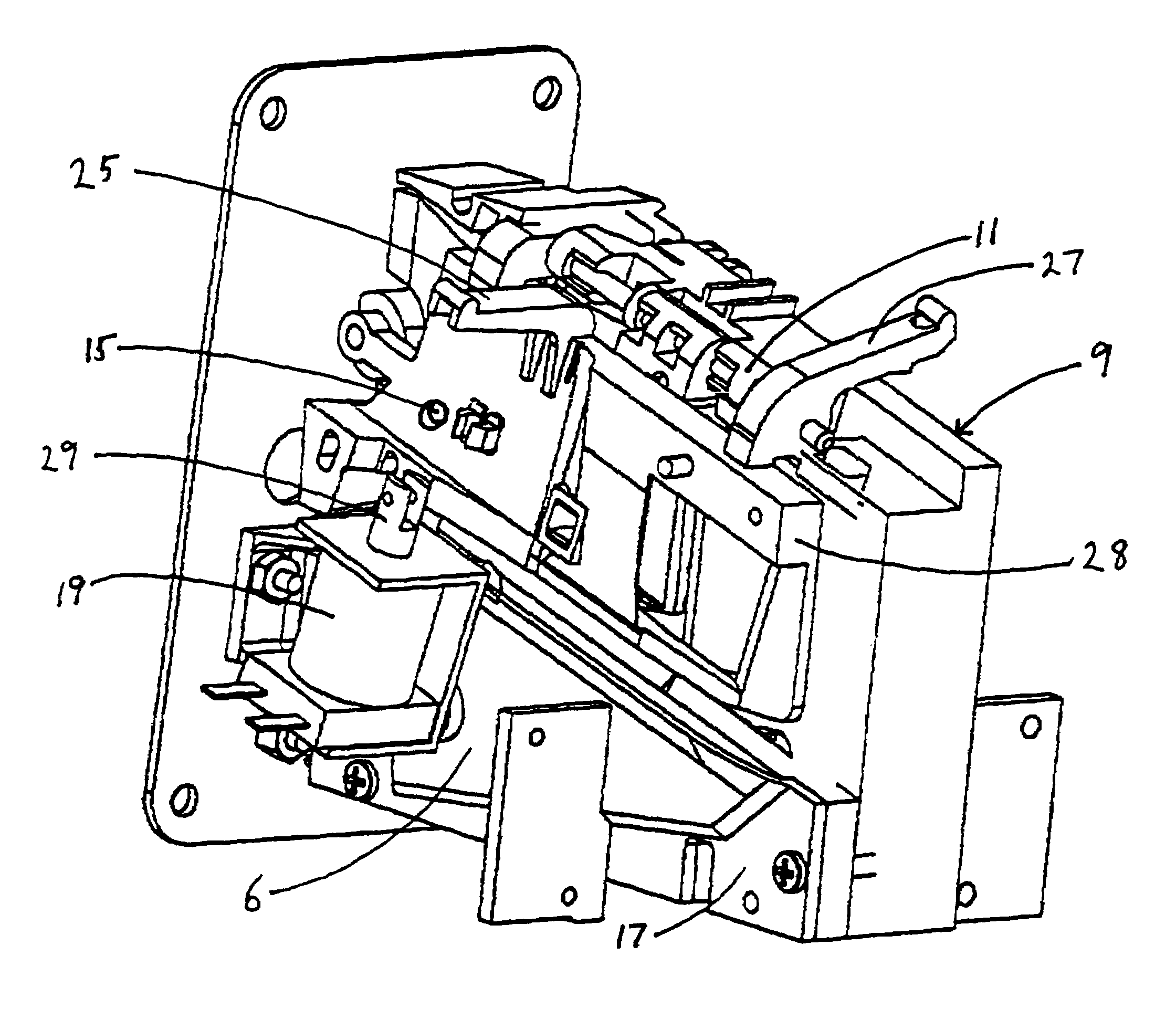
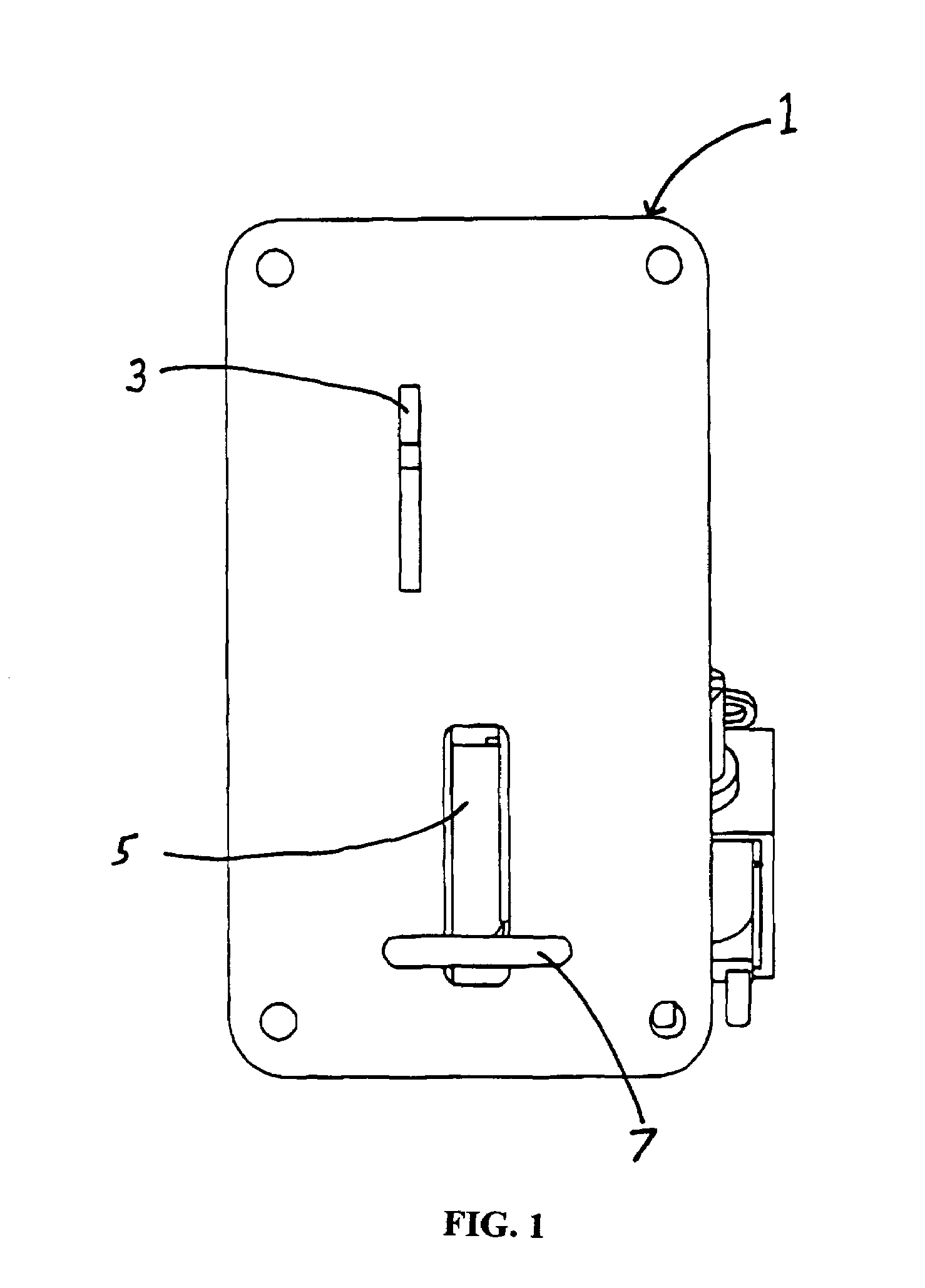
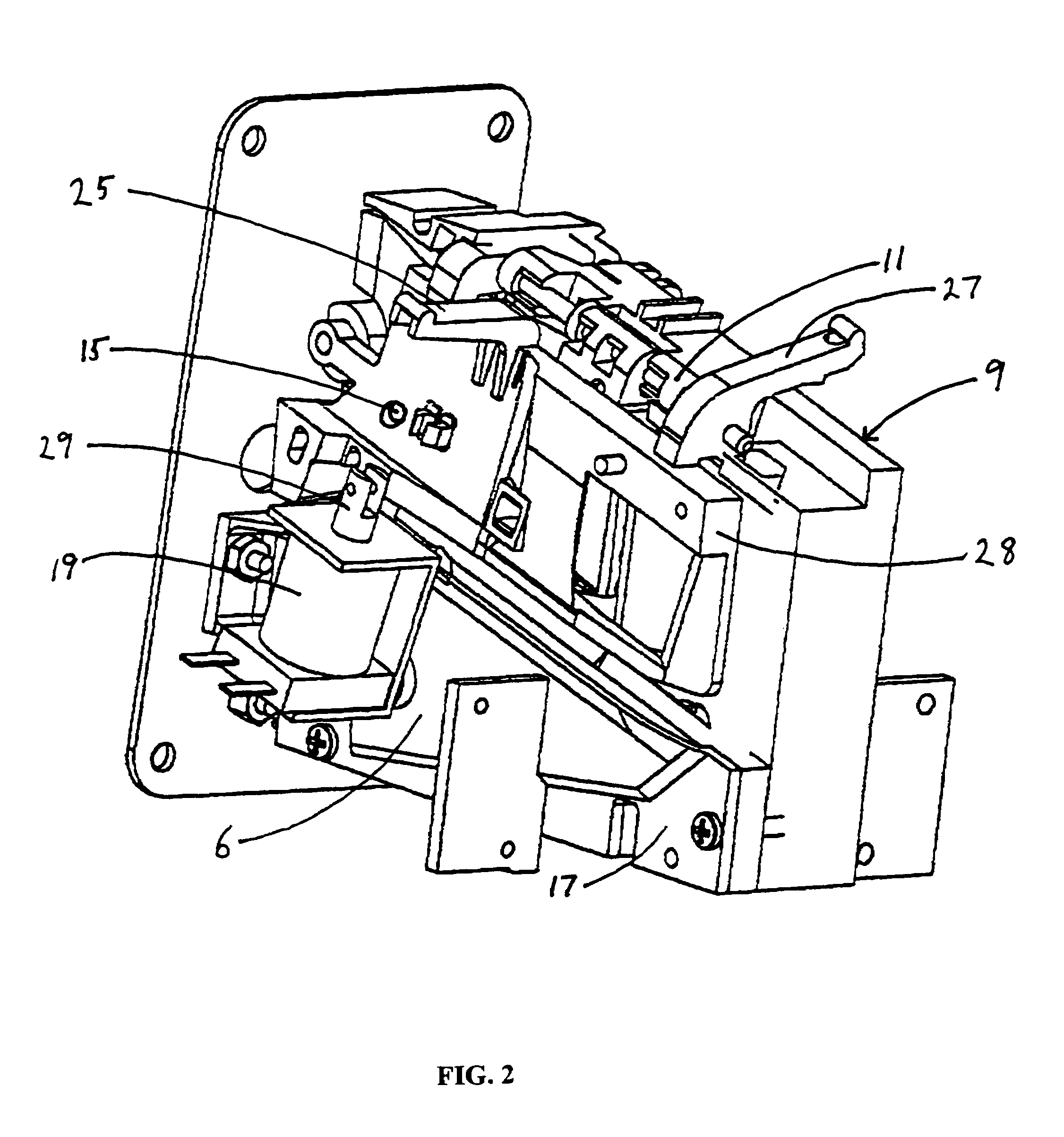
[0015]The present invention is directed to a coin separator and rejector apparatus that will electronically release and return jammed coins, tokens, slugs and the like. The present invention has a coin separator and rejector body (rejector body) having one or more downwardly inclined coin races formed therein. The rejector body has an upstream portion and a downstream portion. In addition, the coin races further comprise a first wall and a second wall wherein at least a portion of one of the race walls is pivotally connected with the rejector body. For example, coin separators and rejectors generally incorporate a coin return button mechanically linked to the device. When the button is depressed, it forces the rejector body to pivot into an open position to allow jammed coins to fall out of the coin race and from the rejector body and into a coin return portion. An example of a coin separator and rejector composed of segments hinged together with a coin path formed between the hinge...


PUM


Abstract

A coin separator and rejector apparatus that will electronically release and return jammed coins, tokens, slugs and the like is disclosed. A coin separator and rejector body is described having one or more downwardly inclined coin races formed therein. The rejector body has an upstream portion and a downstream portion. The coin races further comprise a first wall and a second wall wherein at least a portion of one of the race walls is pivotally connected with the rejector body. A first sensor is located in the upstream portion of the rejector body and a second sensor located in said downstream portion of said rejector body. An actuator is in mechanical connection with the pivotal portion of the race wall. A processor is in electrical communication with the sensors and with said actuator. A coin in an upstream portion of a coin separator and rejector is detected by the first sensor and sends a signal to the processor. The processor is programmed to wait a predetermined period of time to receive a signal from the second sensor indicating that the coin has progressed in the coin race to the second sensor. If the processor receives no signal from the second sensor after a predetermined time period has passed, the processor sends a signal to the actuator to open the pivotally connected portion of the separator and rejector to allow the jammed coin to be released from the separator and rejector.

Description

FIELD OF THE INVENTION[0001]The present invention relates to coin separators and rejectors and more particularly to coin operated machines where selection and rejection of coins is required.BACKGROUND OF THE INVENTION[0002]Coin separators and rejectors are widely employed in coin operated machines such as vending machines, public telephones, video games, car washes, laundromats and the like.[0003]Coin separators and rejectors employ a variety of means to separate coins and to reject unwanted coins, tokens, slugs and the like. For example, U.S. Pat. No. 2,292,628 discloses a rejector wherein a coin inserted into a coin slot engages a series of coin cradles disposed within the apparatus and moves downwards across the face of the rejector via a plurality of coin handling cradles until it reaches a particular coin outlet slot. The disadvantage of this and similar devices is the number of moving parts that can fail due to wear by contamination by dirt and corrosives. This results in nume...

Claims


Application Information

Patent Timeline
Patent Type & Authority Patents(United States)
IPC IPC(8): G07C3/00G07F9/02
CPCG07F1/04G07F1/046
Inventor BRUNER, PHILEMON L.REGENBRECHT, KURT D.MEE, GARY L.
Owner IMONEX SERVICES
Why Eureka
Try Eureka