Composite shear tie

a shear tie and composite material technology, applied in the field of composite shear tie, can solve the problems of complex shape of shear tie and specific load carrying requirements, and the inability to meet the load carrying requirements of composite materials created using current shapes

Inactive Publication Date: 2009-12-22
THE BOEING CO
View PDF17 Cites 37 Cited by
  • Summary
  • Abstract
  • Description
  • Claims
  • Application Information

AI Technical Summary

Problems solved by technology

Shear ties have a complex shape and specific load carrying requirements.
Creating shear ties using composite materials using the current shapes are unable to meet the load carrying requirements.

Method used


Image

  • Composite shear tie
  • Composite shear tie
  • Composite shear tie

Examples


Embodiment Construction

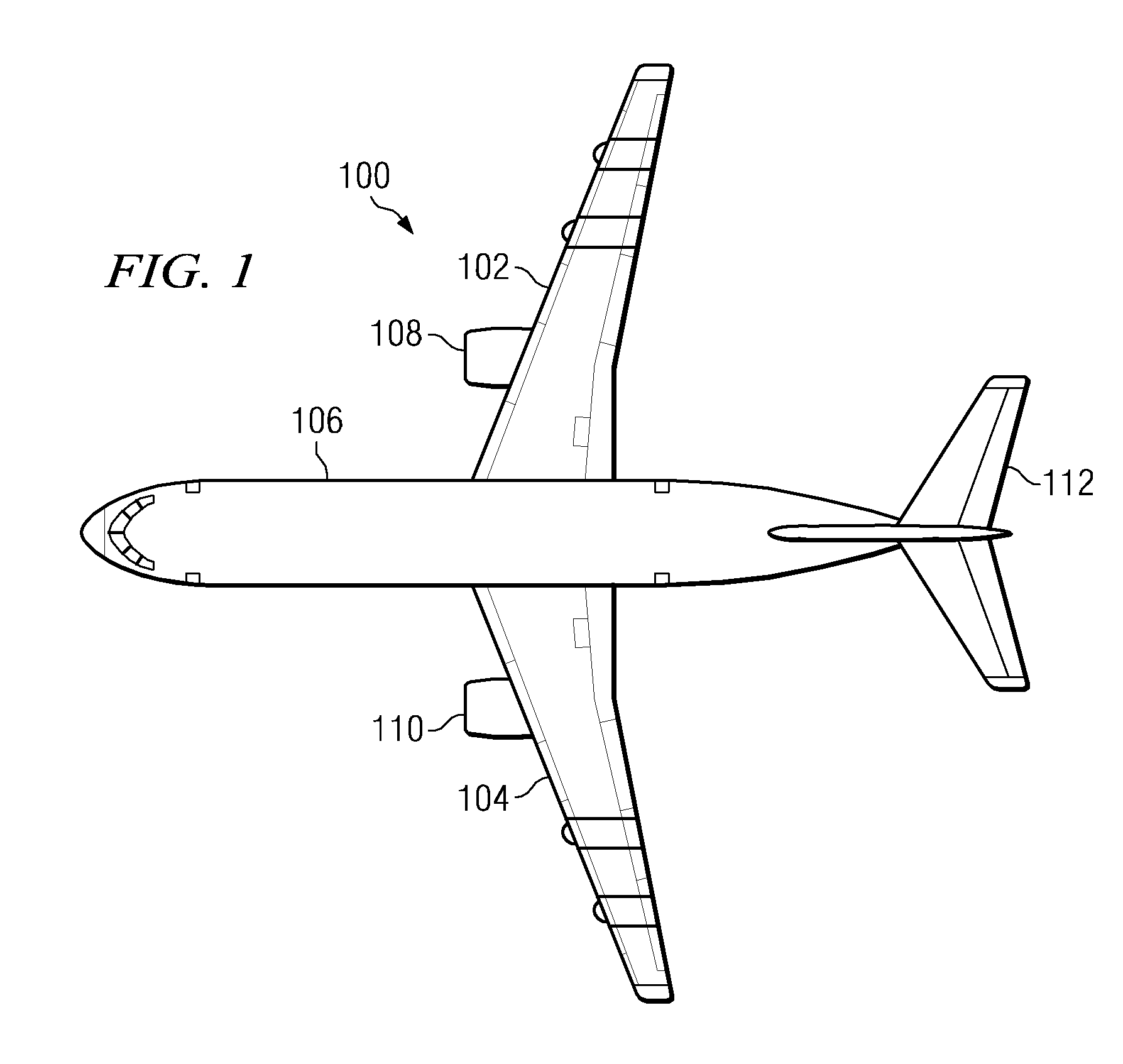
[0027]With reference now to the figures, FIG. 1 is an example of an aircraft in which the advantageous embodiments of the present invention may be implemented. Aircraft 100 is an example of an aircraft in which a method and apparatus for tying a rib to a skin to a wing may be implemented. In this illustrative example, aircraft 100 has wings 102 and 104 attached to body 106. Aircraft 100 includes wing mounted engine 108, wing mounted engine 110, and tail 112. The different advantageous embodiments include composite shear ties used to connect ribs within wings 102 and 104 to skin panels for the wings.

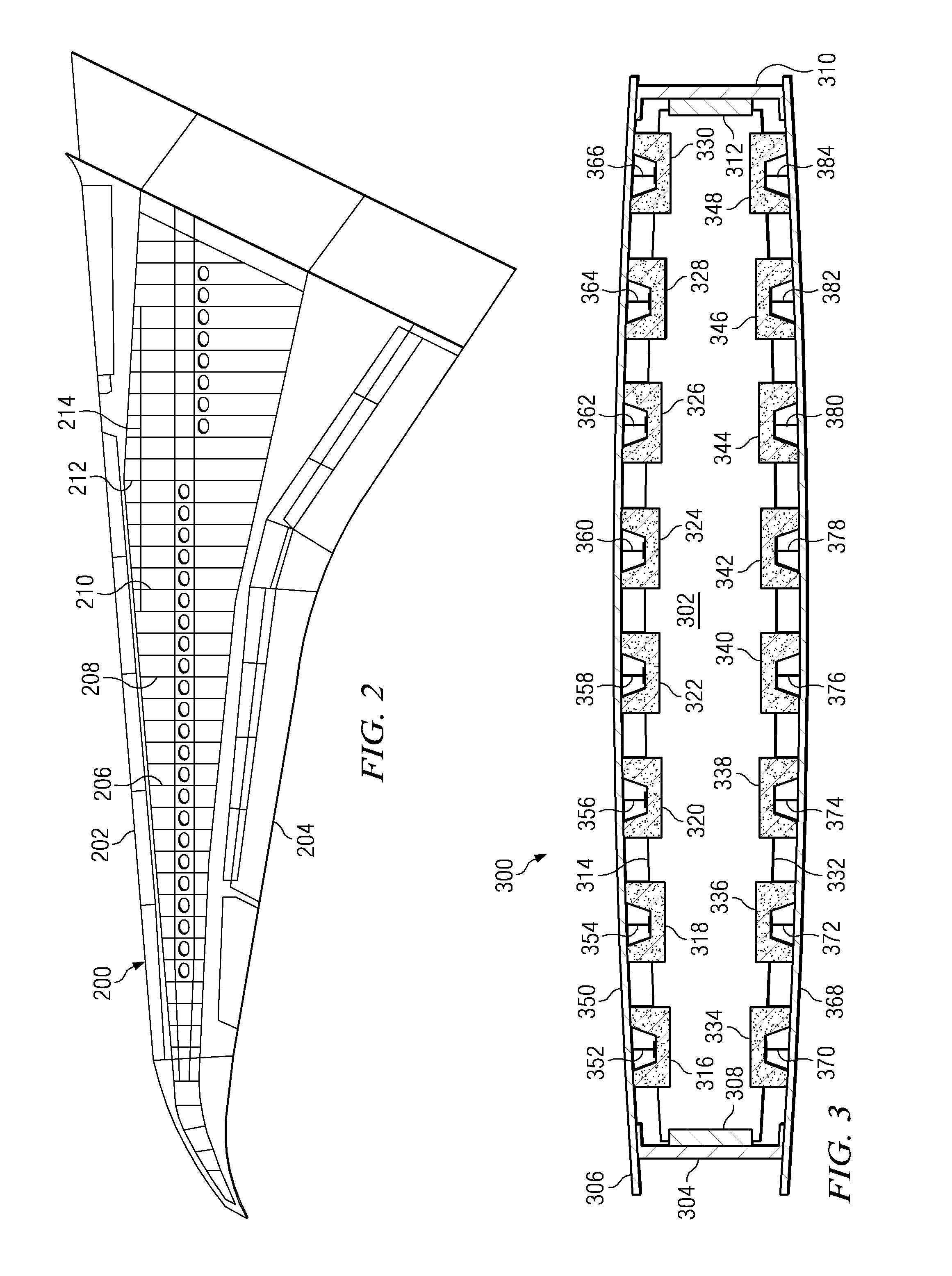
[0028]Turning now to FIG. 2, a diagram illustrating a top view of a wing is depicted in accordance with an advantageous embodiment of the present invention. In this particular example, wing 200 is a more detailed example of wing 104 in FIG. 1. In this particular example, wing 200 has a front edge 202 and a rear edge 204. Ribs 206, 208, 210, and 214 are examples of ribs in which composite ...


PUM


Abstract

A composite shear tie for connecting a rib in a wing of an aircraft to a skin panel. The shear tie includes a web section having a first edge, a second edge, and a third edge. The web section is formed from a composite material. The first edge is parallel to the second edge, and the web section is configured to be connected to the rib in the wing of the aircraft. The shear tie also has a first free flange extending from the first edge, wherein the first free flange is around perpendicular to the web section and wherein the first free flange is formed from the composite material. A second free flange is present in the shear tie in which the second free flange extends from the second edge, wherein the second free flange is around perpendicular to the web section and wherein the second free flange is formed from the composite material. The shear tie has a base flange section extending from the third edge, wherein the first base flange is configured for attachment to the skin panel and wherein the first base flange is formed from the composite material.

Description

BACKGROUND INFORMATION[0001]1. Field of Invention[0002]The present invention relates generally to aircraft and in particular to connecting components to each other in an aircraft. Still more particularly, the present invention relates to a shear tie for use in a wing rib.[0003]2. Background Description[0004]Composite materials are quickly replacing aluminum in aircraft. Composite materials provide weight savings and increased durability. In the design and manufacture of new aircraft, even the wing and fuselage are now being designed to use advanced composite materials. These materials include, for example, graphite combined with a toughened epoxy resin and titanium and graphite composites. An additional advantage of using composite materials is reducing electromagnetic effects (EMEs), such as those from lightning strikes.[0005]Newer designs employ composite structural components in the wings, such as composite ribs and spars. Additionally, the skin panels used for the wing also are ...

Claims


Application Information

Patent Timeline
Patent Type & Authority Patents(United States)
IPC IPC(8): B64C3/26B64C1/12
CPCB64C3/26B64C3/182
Inventor PHAM, DOAN D.TOLLAN, MARK W.
Owner THE BOEING CO
Why Eureka
Try Eureka