Instrument panel structure with airbag unit

an instrument panel and airbag technology, which is applied in the direction of pedestrian/occupant safety arrangement, vehicle components, vehicular safety arrangments, etc., can solve the problem of a location of the airbag unit, the front end portion of the airbag cannot be properly inflated in a space, and the gap between the front end portion of the airbag and the front end of the windshield or the upper face portion of the instrument panel is relatively larg

Inactive Publication Date: 2010-02-09
MAZDA MOTOR CORP
View PDF20 Cites 9 Cited by
  • Summary
  • Abstract
  • Description
  • Claims
  • Application Information

AI Technical Summary

Benefits of technology

[0006]The present invention has been devised in view of the above-described problems, and an object of the present invention is to provide an instrument panel structure with an airbag unit that can perform a proper protection of the passenger seated in the assistant seat.
[0008]According to the above-described structure, when the airbag is inflated by the operation of the airbag unit at the vehicle frontal crash, the tear line is torn by the inflation pressure of the airbag and then the lid portion opens forward substantially around the hinge member. Since the lid portion opens beyond the difference-in-level portion to the position where the lid portion is substantially located on the front upper face portion of the instrument panel when the airbag is inflated to its maximum opening state, the front end portion of the airbag can be inflated properly in the space between the windshield and the upper face portion of the instrument panel. Namely, the lid portion opens without hitting against the difference-in-level portion and with smoothly rotating beyond the difference-in-level portion, and then substantially an entire part of the outside face of the lid portion contacts the outside face of the front upper face portion of the instrument panel eventually. Accordingly, the front end portion of the airbag can be inflated properly in the space between the windshield and the upper face portion of the instrument panel without the prevention by the lid portion. Thereby, the improper forward shift of the inflated airbag by the passenger hitting against the airbag can be prevented and thus the proper protection of the passenger can be performed.
[0012]According to the above-described embodiments, the hinge member can be accommodated compactly and the above-described forward opening of the lid portion can be achieved surely and easily.
[0014]Accordingly, the expansion of the hinge member can be provided to a proper extent, so the above-described function and effect of the present invention can be performed more properly.
[0018]Accordingly, since the indication portion is positioned at relatively a high level portion of the instrument panel, the proper visibility of the indication portion can be provided. Also, since the indication portion is provided at the recessed connecting portion, the lid portion can be surely prevented from hitting against the indication portion. Thus, any breakage of the indication portion or any scatter of broken pieces of the indication portion can be properly prevented.

Problems solved by technology

Herein, in providing the airbag unit inside the instrument panel with the above-described difference-in-level, there may be a problem of a location of the airbag unit.
Meanwhile, in a case where the airbag unit is provided at a rear portion inside the rear upper face portion of the instrument panel, the airbag would be inflated so rearward that a front end portion of the airbag would not be inflated properly in a space between a windshield and the upper face portion of the instrument panel.
As a result, there would occur a relatively large gap between the front end portion of the airbag and front ends of the windshield or the upper face portion of the instrument panel when the airbag is inflated to its maximum opening state.
This gap may cause a forward shift of the inflated airbag by the passenger hitting against the airbag, so that the protection of the passenger by the airbag would be improperly delayed.
Although the airbag with a large volume could prevent this delayed protection, such airbag would require an improperly long time for its full inflation instead.
There is also a concern that the lid portion would be broken and pieces of the broken lid portion would scatter.

Method used


Image

  • Instrument panel structure with airbag unit
  • Instrument panel structure with airbag unit
  • Instrument panel structure with airbag unit

Examples


Embodiment Construction

[0026]Hereinafter, preferred embodiments of the present invention will be described referring to the accompanying drawings.

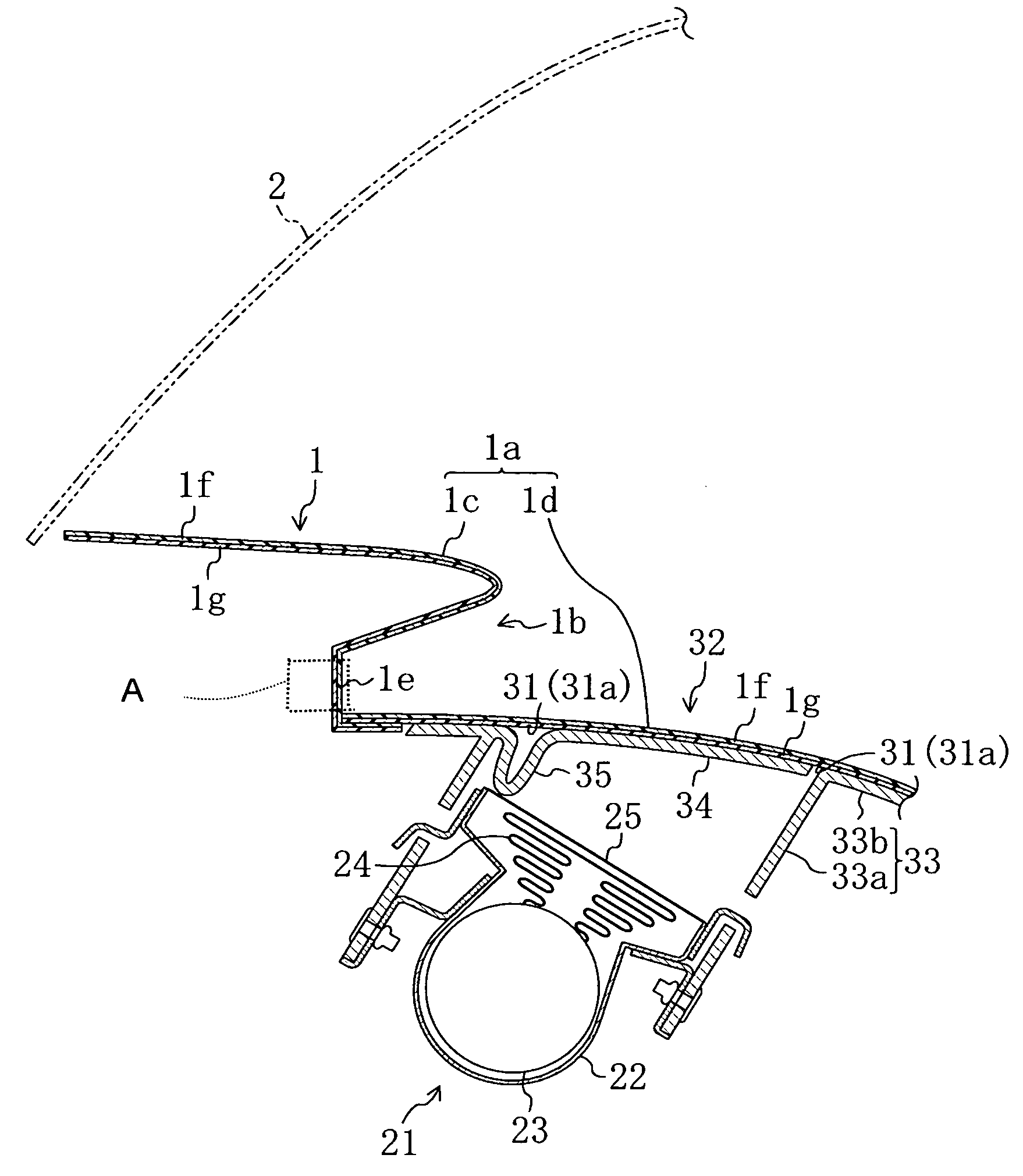
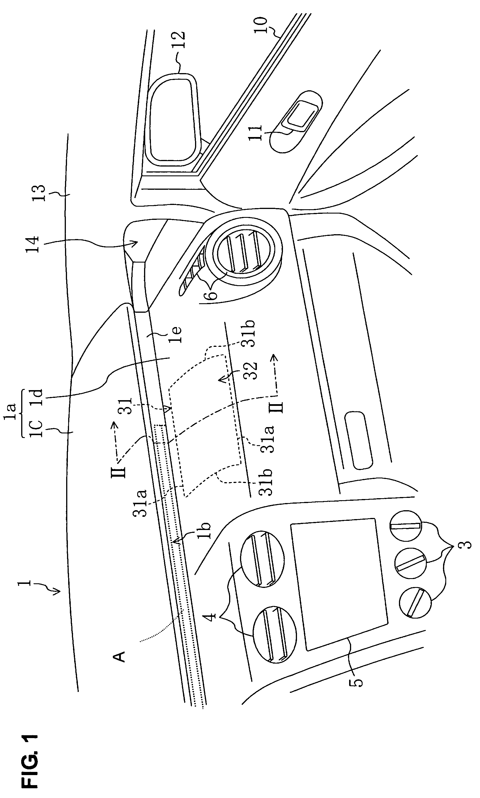
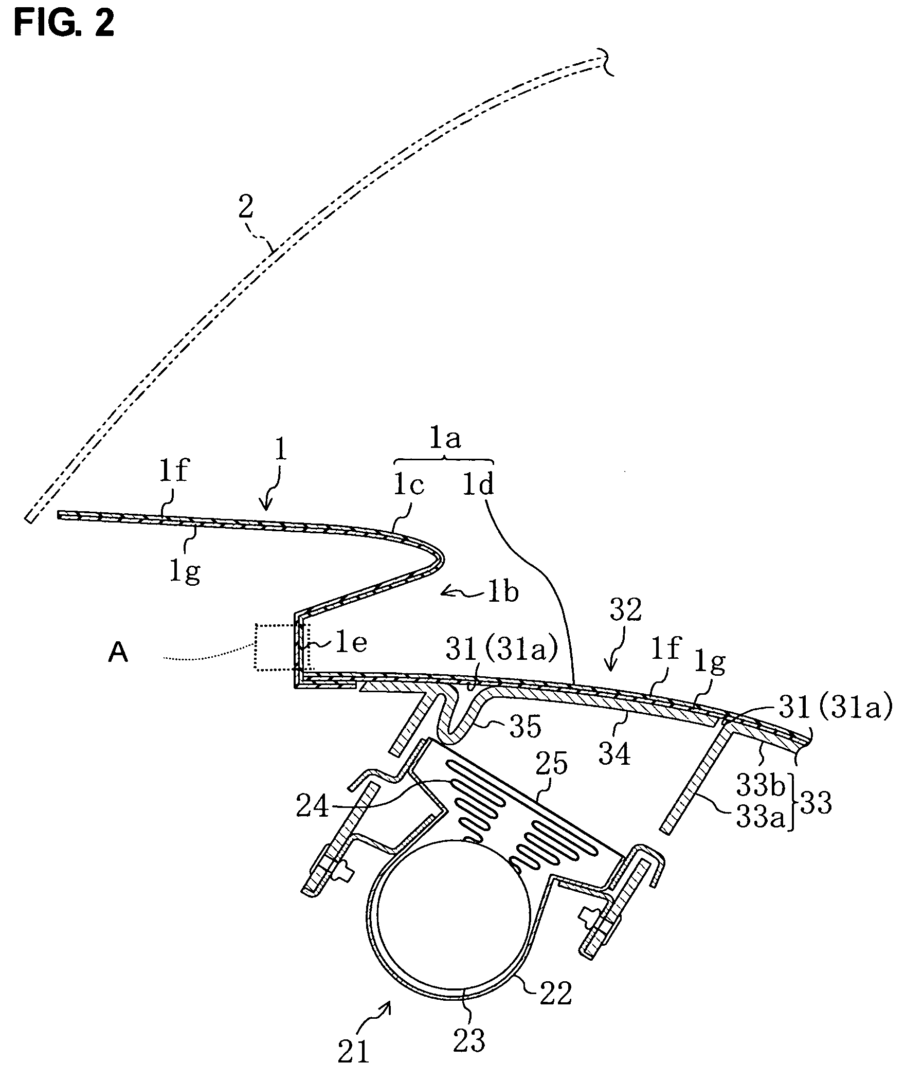
[0027]FIG. 1 is a perspective view of a front end portion of a vehicle cabin on an assistant seat side of a vehicle (with a left-positioned steering wheel) with an instrument panel structure according to an embodiment of the present invention, and FIG. 2 is a sectional view taken along line II-II of FIG. 1. A difference-in-level portion 1b is formed on an upper face portion 1a of an instrument panel 1, which is located below a windshield 2, at substantially a central portion of the upper face portion 1a in a vehicle longitudinal direction. A rear portion 1d of the upper portion 1a that is located in back of the difference-in-level portion 1b is located at a lower level than a front portion 1c of the upper portion 1a that is located in front of the difference-in-level portion 1b. In the present embodiment, a vertical distance (namely, a height of the difference-i...


PUM


Abstract

The airbag unit is disposed inside the rear upper face portion of the instrument panel near the difference-in-level portion. The lid portion is configured to open substantially forward around the hinge member without hitting against the difference-in-level portion. Herein, the hinge member is configured such that the lid portion can open beyond the difference-in-level portion to the position where the lid portion is substantially located on the front upper face portion of the instrument panel when the airbag is inflated to its maximum opening state. Accordingly, the proper protection of the passenger seated in the assistant seat can be performed.

Description

BACKGROUND OF THE INVENTION[0001]The present invention relates to an instrument panel structure with an airbag unit, which is provided at a front end portion in a vehicle cabin.[0002]Conventionally, it is well known that an airbag unit with an airbag that is inflated to protect a passenger seated in an assistant seat at a vehicle frontal crash is provided inside an instrument panel that is provided at a front end portion in a vehicle cabin. Herein, the following structure, as disclosed, for example, in Japanese Patent Laid-Open Publication No. 2005-088634, is known. That is, a lid portion is formed on an upper face portion of the instrument panel at a portion corresponding to the airbag unit, wherein the lid-portion is partitioned by a tear line with a groove that is formed on an inside face of the upper portion and configured to open when the tear line is torn by an inflation pressure of the airbag. And, a frame portion is attached to the inside face of the upper portion, wherein t...

Claims


Application Information

Patent Timeline
Patent Type & Authority Patents(United States)
IPC IPC(8): B60R21/205B60R21/20B60R21/215
CPCB60R21/2165B60R21/205B60R2021/21537
Inventor SADANO, MASATOYAMANISHI, MITSUTOSHI
Owner MAZDA MOTOR CORP
Why Eureka
Try Eureka