Hose fitting inserter

a technology of inserters and hoses, which is applied in the direction of metal-working equipment, metal-working equipment, manufacturing tools, etc., can solve the problems of inability to service a hose located adjacent to or inside a piece of machinery, not only difficult to use and lack of portability, and not being able to repair a hose in “mid-air” typically

Inactive Publication Date: 2010-02-23
BENSON JOY FRANCES
View PDF23 Cites 29 Cited by
  • Summary
  • Abstract
  • Description
  • Claims
  • Application Information

AI Technical Summary

Benefits of technology

[0021]A primary advantage of the present invention is that a method and apparatus are provided which enables hose fittings to be inserted into hoses of multiple diameters, even when the hose is in an area which is relatively difficult to access.
[0022]An embodiment of the present invention also relates to a an apparatus having a mounting bar, a fitting inserter attached to a first end of the mounting bar, the fitting inserter having a translationally movable shaft, and a hose securer comprising a clamp, said clamp adapted to hold a portion of a hose in place. In one embodiment, the fitting inserter includes a pad and / or one or more protrusions for holding a fitting. The clamp can include a strap and / or a compression plate. Further, the compression plate can have a curve and / or one or more textured surfaces.
[0023]An embodiment of the present invention also relates to a fitting insertion apparatus having a hose securer that includes an elongated surface for placement of at least a portion of a hose; and a fitting inserter having a translationally movable shaft. The hose securer can also include a clamp. The clamp can include a strap. The translationally movable shaft can be hand-powered, electrically-powered, pneumatically-powered, and / or hydraulically-powered.
[0024]Other objects, advantages and novel features, and further scope of applicability of the present invention will be set forth in part in the detailed description to follow, taken in conjunction with the accompanying drawings, and in part will become apparent to those skilled in the art upon examination of the following, or may be learned by practice of the invention. The objects and advantages of the invention may be realized and attained by the instrumentalities and combinations particularly pointed out in the appended claims.

Problems solved by technology

Further, devices currently known are not only difficult to use and lack portability, but also make it impossible to service a hose located adjacent to or inside a piece of machinery.
Since repair of hoses in “mid-air” is not typically possible with the devices of the prior art, and because hoses are typically located adjacent to or inside a piece of machinery, a user is often forced to remove an entire section of hose.

Method used


Image

  • Hose fitting inserter
  • Hose fitting inserter
  • Hose fitting inserter

Examples


Embodiment Construction

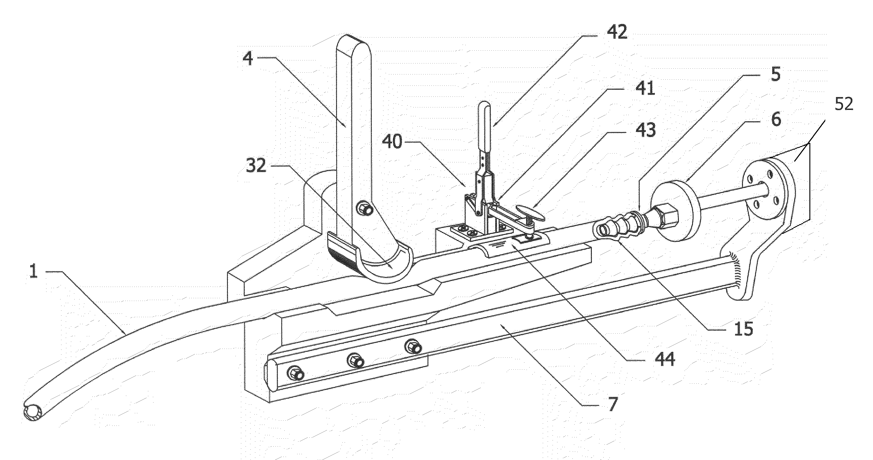
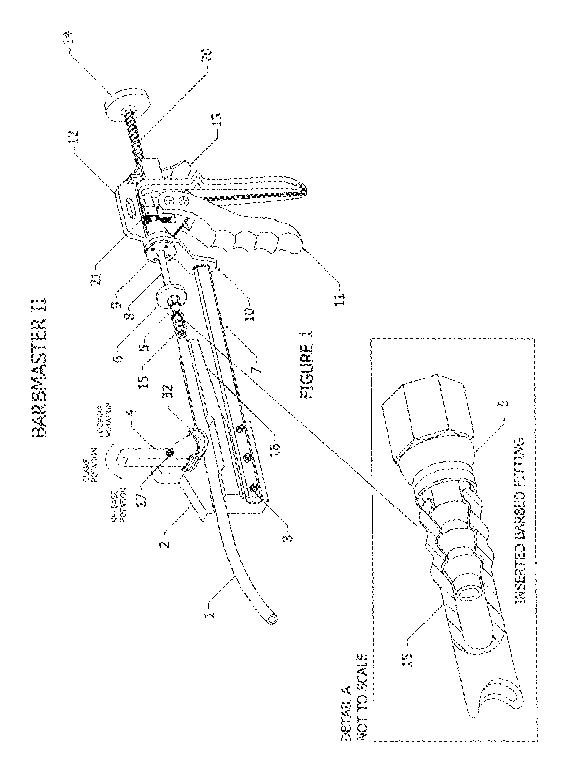
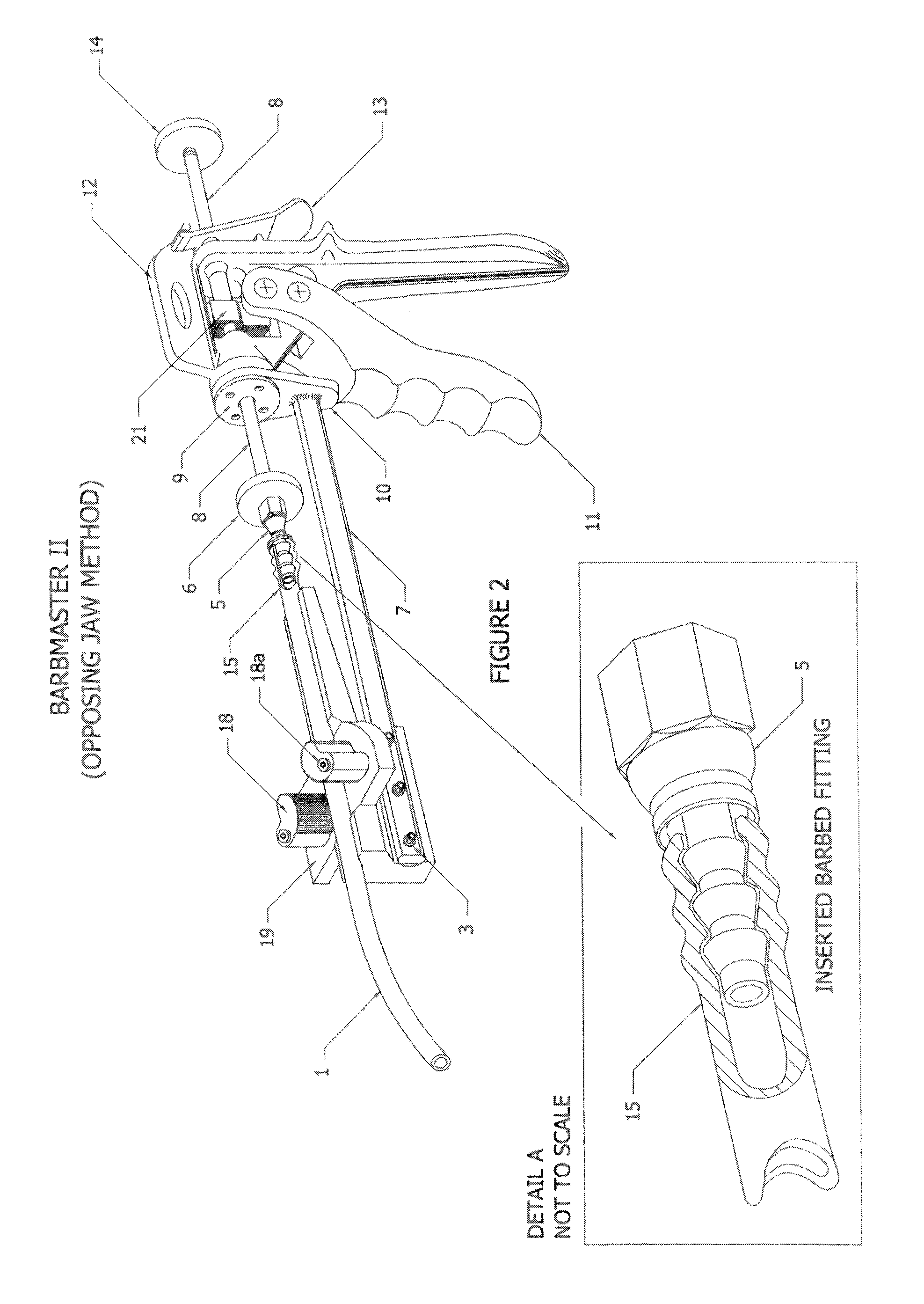
[0025]The term “hose” as used throughout the specification, is meant to encompass all forms of hoses, tubes, and piping, including, but not limited to all forms of flexible and semi-flexible piping. The term “v-shaped channel” as used throughout the specification of the present invention, has been chosen solely for the purpose of maintaining consistency, and can also include any such apparatus which would perform a similar function such as a u-shaped channel, a flat plate, a completely or substantially enclosed structure such as a pipe, etc. Although the apparatus of the present invention is relatively small and thus readily portable, the apparatus of the present invention can also be secured to a base structure with the aid of a table-vise and / or fasteners and fastening methods readily understood to those skilled in the art. While the present invention teaches the use of a pad for pressing a fitting into a hose end, it is not mandatory that such surface be padded. Rather, this padd...


PUM


Abstract

A powered or hand-activated stationary and/or portable hose fitting insertion apparatus and method. A hose is preferably held in place with a clamp, strap or other apparatus on a platform or in a trough and a fitting is caused to be inserted into an end of the hose by a force applied to the fitting from a pad.

Description

CROSS-REFERENCE TO RELATED APPLICATIONS[0001]This application is a continuation-in-part application of U.S. patent application Ser. No. 10 / 940,203, entitled “Portable Hose Fitting Inserter,” filed on Sep. 13, 2004, which claimed priority of U.S. Provisional Patent Application Ser. No. 60 / 539,558, entitled “Hose Fitting Inserter,” filed on Jan. 27, 2004, and which is a continuation-in-part application of U.S. patent application Ser. No. 10 / 732,675, entitled “Method and Apparatus for Installing Hose Fittings,” to Joel Kent Benson, filed on Dec. 9, 2003, now abandoned, which itself is a continuation-in-part application of U.S. patent application Ser. No. 10 / 074,570, entitled “Hose Fitting Insertion Apparatus,” to Benson, filed on Feb. 12, 2002, and issued as U.S. Pat. No. 6,658,711 on Dec. 9, 2003, and the specifications and claims of those applications are incorporated herein by reference.BACKGROUND OF THE INVENTION[0002]1. Field of the Invention (Technical Field)[0003]The present inv...

Claims


Application Information

Patent Timeline
Patent Type & Authority Patents(United States)
IPC IPC(8): B23P19/04
CPCB25B27/10
Inventor BENSON, JOEL KENT
Owner BENSON JOY FRANCES
Why Eureka
Try Eureka