
Optical device, and method of measuring the dimension of object using optical device

a technology of optical devices and optical devices, which is applied in the direction of distance measurement, instruments, material analysis, etc., can solve the problems of limiting the measuring places within a reach of the measurer, limiting the measuring places, and cracks in the bridge beam or the top ceiling of the tunnel being incapable of being measured

Inactive Publication Date: 2010-02-23
KANSAI KOUJI SOKURYOU +1
View PDF9 Cites 6 Cited by
  • Summary
  • Abstract
  • Description
  • Claims
  • Application Information

AI Technical Summary

Problems solved by technology

Disadvantageously, this measurement limits the measuring places within a reach of the measurer.
This also limits the measuring places within a range of the rod, so that the cracks on the bridge beam or the top ceiling of the tunnel are incapable of being measured even by this device.
Accordingly, there is no option other than to use a vehicle designed exclusively for works at elevated places or a ladder for measuring cracks occurred on higher portions of the concrete structure, which requires much time for the crack measurement.
Still, the cracks on higher places outside the reach of the vehicle or the ladder are unable to be measured.

Method used


Image

  • Optical device, and method of measuring the dimension of object using optical device
  • Optical device, and method of measuring the dimension of object using optical device
  • Optical device, and method of measuring the dimension of object using optical device

Examples


Embodiment Construction

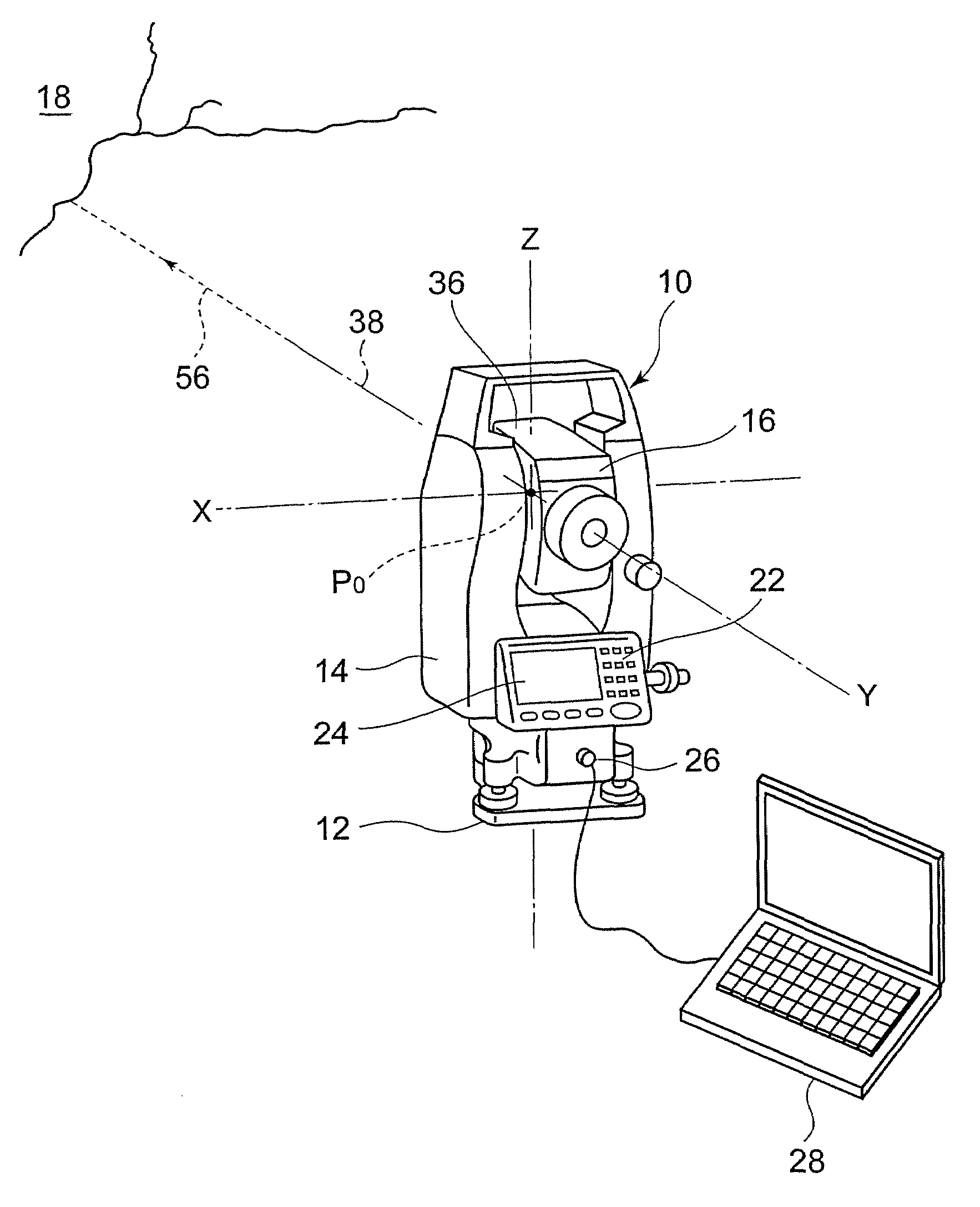
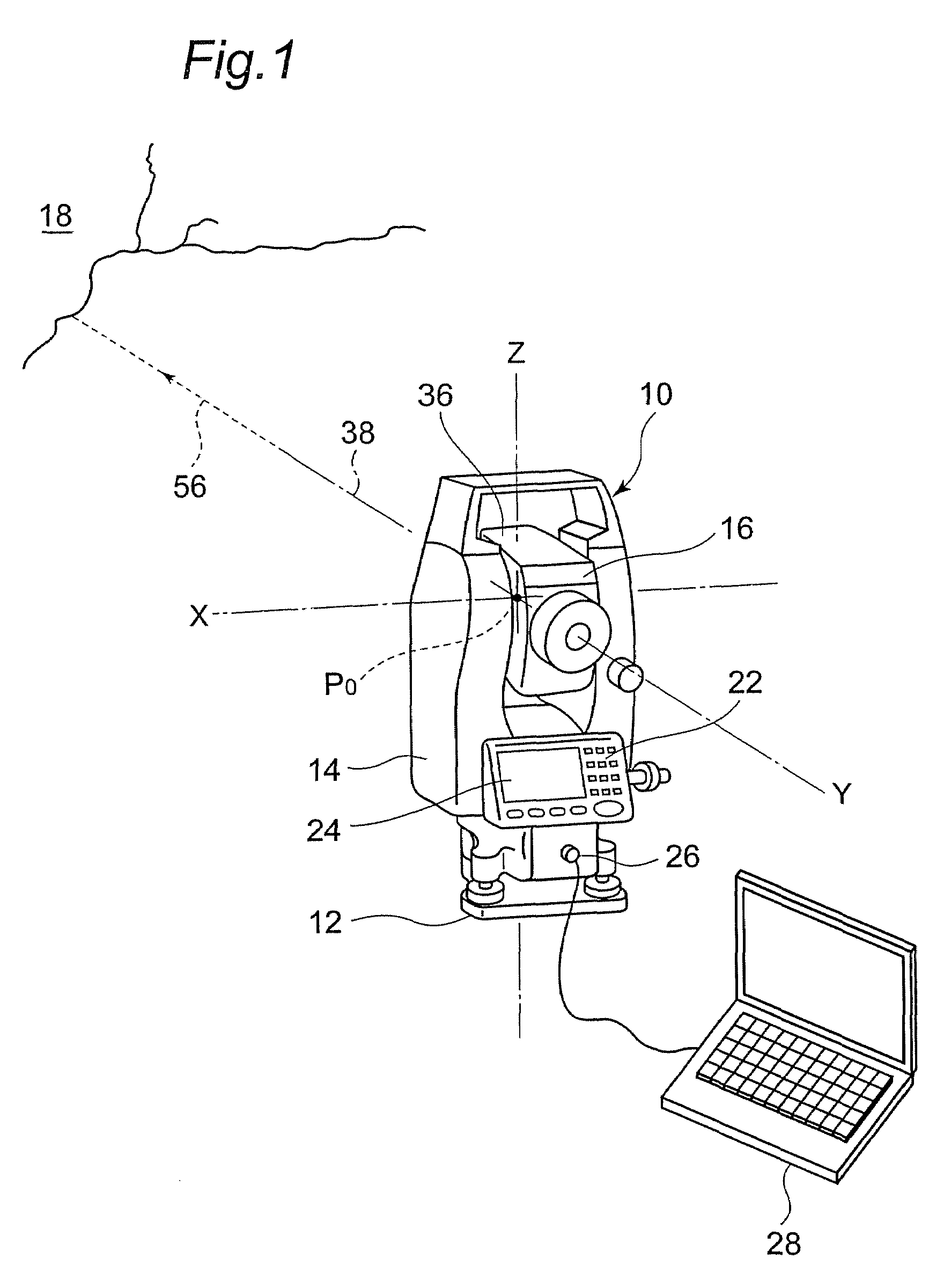
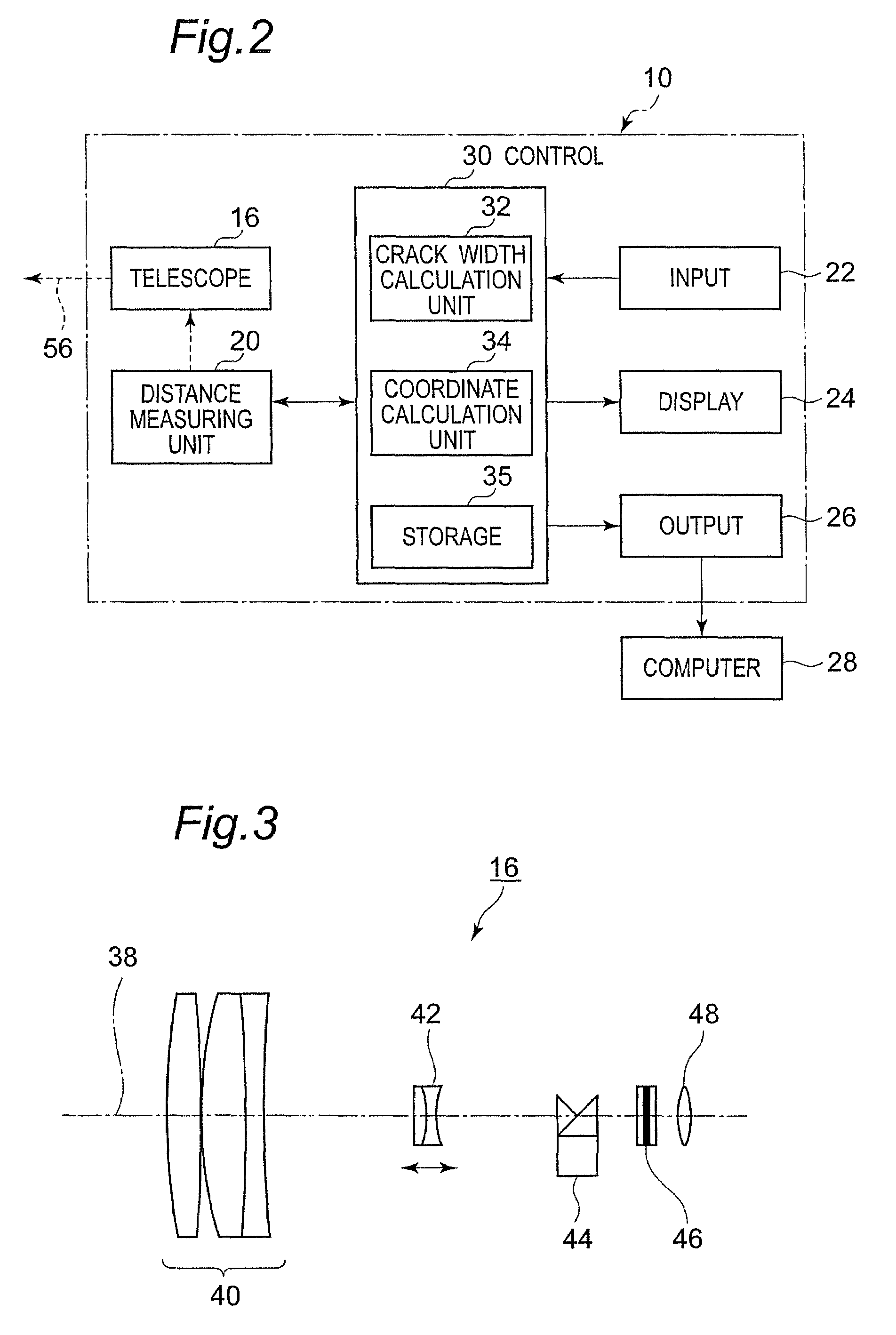
[0063]With reference to the accompanying drawings, discussions will be made to an optical apparatus according to the present invention and a method for measuring the dimensions of an object by using such an optical apparatus. In this application, “an optical apparatus” includes a telescopic apparatus, a collimating apparatus with a telescope, and a measuring apparatus with a collimation function and a distance measuring function. The “object” is not limited to an independent object with a certain dimension and may be a part or portion of the object, such as a part of a crack occurred in the concrete structure. To facilitate the understanding of the invention, a following discussion will be made to an embodiment in which the invention is incorporated in the measuring apparatus and a method for measuring a dimension such as a width of the crack occurred in the concrete structure by using the measuring apparatus.

1-1: Measuring Apparatus

[0064]FIG. 1 shows a laser measuring device, or to...


PUM


Abstract

A device and a method for measuring the sizes of a remote object, for example, concrete crack, without using a high-place work vehicle or a ladder. An optical apparatus (e.g. a measuring device (10) ) used for this purpose is provided with a telescope (16) having a reticule plate (46) . The reticule plate (46) is provided with a plurality of reference scales (52) used for comparison with the size (W) of the image (C′) of an object (C) projected onto the reticule plate (46). The size of the object can be measured using the size of the object image measured with the reference scales (52) and a distance (a distance from a reference point P0 a to the object) measured with a distance measuring unit (20) of the optical apparatus.

Description

TECHNICAL FIELD[0001]The present invention relates to an optical apparatus and, in particular, to an optical apparatus which is preferably used for measuring dimensions of objects such as widths of cracks occurred on a surface of a concrete structure. The present invention also relates to a method for measuring dimensions of objects by using the optical apparatus.BACKGROUND OF THE INVENTION[0002]One of the methods for diagnosing the degree of degradation of a concrete structure, such as a bridge, a tunnel, and a building, includes a measurement of widths of cracks (i.e., dimensions in a direction perpendicular to a crack progressing direction) occurred on the surface of concrete. The typical method for measuring the crack widths uses a conventional scale or a crack scale exclusively designed for crack measurement which is placed on the concrete surface to visually measure the crack width. Disadvantageously, this measurement limits the measuring places within a reach of the measurer....

Claims


Application Information

Patent Timeline
Patent Type & Authority Patents(United States)
IPC IPC(8): G01C3/08
CPCG01C15/002G01B5/0021G01B11/026G01N2203/006
Inventor NAKANIWA, KAZUHIDE
Owner KANSAI KOUJI SOKURYOU
Learn More