Hybrid construction machine

a construction machine and hybrid technology, applied in the direction of battery/cell propulsion, fluid coupling, coupling, etc., can solve the problems of inability to operate the hybrid excavater, difficulty in adjusting the operating position, and inability to adjust the operating position, so as to achieve similar operating capabilities and sacrifice the effect of operability

Active Publication Date: 2010-03-02
KOBELCO CONSTR MASCH CO LTD
View PDF5 Cites 41 Cited by
  • Summary
  • Abstract
  • Description
  • Claims
  • Application Information

AI Technical Summary

Benefits of technology

[0017]An object of the present invention is to provide a hybrid construction machine capable of achieving substantially the same performance and operability as those of an equivalent hydraulic excavator. Another object of the present invention is to protect an electric storage device and to prevent engine stalling.
[0018]According to an aspect of the present invention, a hybrid construction machine includes an engine, a hydraulic pump connected to an output shaft of the engine, a hydraulic actuator driven by the hydraulic pump, a generator motor connected to the output shaft of the engine to perform a generator function and a motor function, an electric actuator, operation units for operating the respective actuators, an electric storage device which supplies and receives electric power to and from the generator motor and the electric actuator, and a controller for controlling outputs of the hydraulic pump and the electric actuator. The controller detects power consumption of each of the hydraulic pump and the electric actuator. Also, the controller controls the outputs of the hydraulic pump and the electric actuator so that the sum of the detected power consumption does not exceed maximum supply power set as the sum of power that can be supplied to the hydraulic pump and the electric actuator.
[0019]In the present invention, maximum supply power is set and the sum of the outputs of the hydraulic pump and the electric actuator is limited so as not to exceed the set maximum supply power. This maximum supply power is set to be substantially the same as the maximum power of a hydraulic construction machine of the same type and with similar operation capabilities to those of the hybrid construction machine of the present invention. Therefore, the hybrid construction machine of the present invention can protect the electric storage device while providing substantially the same performance and operability as those of the equivalent hydraulic construction machine.

Problems solved by technology

This deficiency in engine power is made up by the electric storage device via the generator motor.
A problem to be solved by the hybrid excavator is how to provide substantially the same performance and operability as those of a hydraulic excavator with equivalent operating capabilities.
This can be uncomfortable for an operator who is familiar with the operation of the hydraulic excavator.
In this respect, the operability of the hybrid excavator becomes worse.
At the same time, even if the maximum system power of the hybrid excavator is set to be higher than the maximum power of the equivalent hydraulic excavator, the maximum system power may be insufficient in the case that a load exceeding the set maximum system power is applied.
However, in the hybrid excavator, which includes the electric storage device as a drive source in addition to the engine, the electric storage device may cause an abnormal voltage drop or over-discharge thereof in an attempt to respond to the applied load.
This may shorten the life of the electric storage device or cause damage to the electric storage device.
Moreover, if the amount of assist supplied from the electric storage device is insufficient, an excessive load applied to the engine may cause engine stalling.
This problem becomes apparent when the hydraulic actuator and the electric actuator are simultaneously operated, because the total loads increase.
However, this technique achieves only a function of efficiently using a small engine, that is, the originally intended function of the hybrid construction machine.
Since this causes unnecessary degradation in operating performance of the hybrid construction machine, its primary object of providing substantially the same performance as that of the equivalent hydraulic construction machine cannot be achieved.

Method used


Image

  • Hybrid construction machine
  • Hybrid construction machine
  • Hybrid construction machine

Examples


first embodiment

See FIG. 1 to FIG. 4

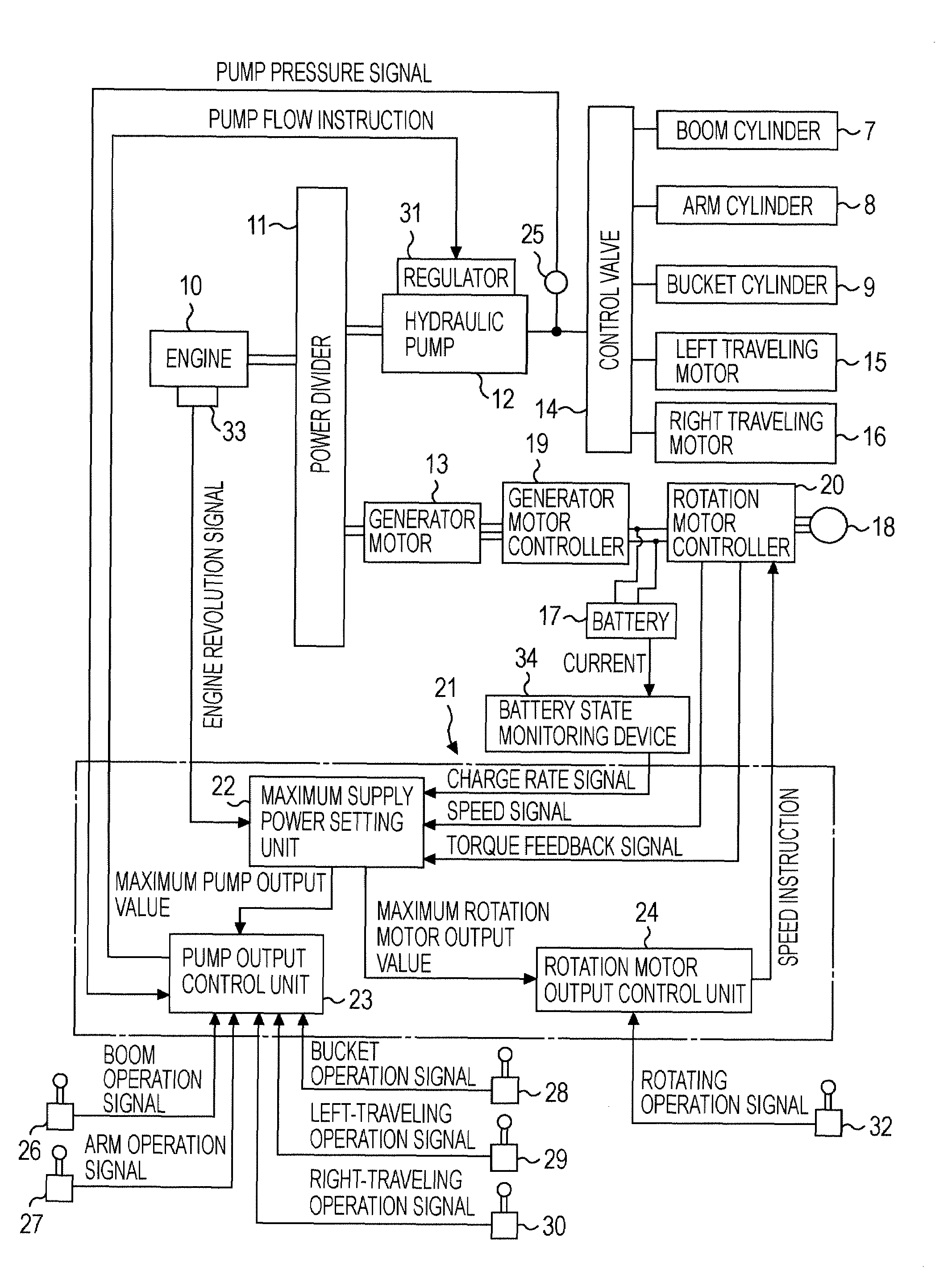
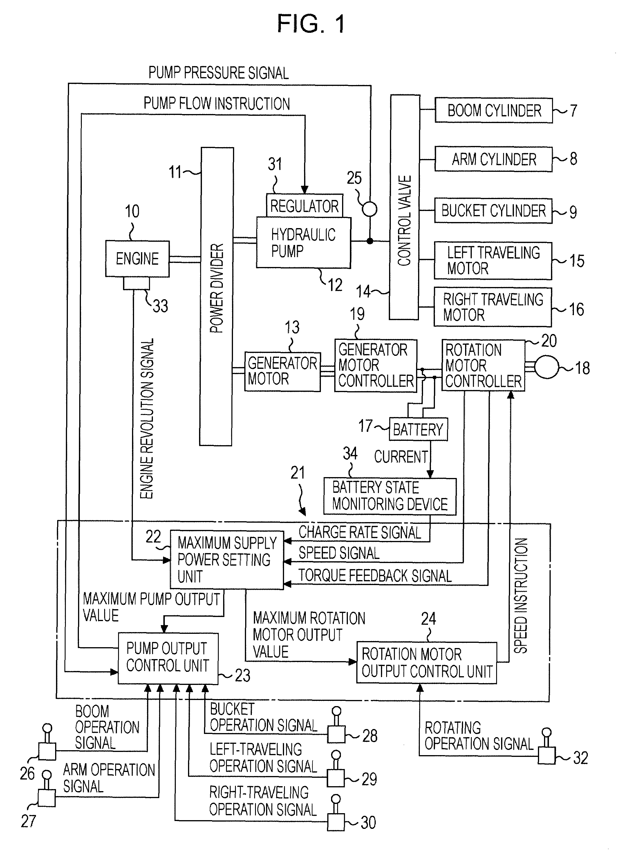
[0037]FIG. 1 is a block diagram of a hybrid excavator according to the present embodiment. As illustrated in FIG. 1, a hydraulic pump 12 and a generator motor 13 which serves both a generator function and a motor function are connected in parallel through a power divider 11 to an engine 10. The hydraulic pump 12 and the generator motor 13 are driven by the engine 10. A plurality of hydraulic actuators is connected through a control valve 14 to the hydraulic pump 12. The control valve 14, which is illustrated as a single entity in FIG. 1, represents a plurality of control valves for the respective hydraulic actuators. The hydraulic actuators include a boom cylinder 7, an arm cylinder 8, a bucket cylinder 9 (equivalent to the cylinders 7, 8, and 9 of FIG. 8), a left traveling motor 15, and a right traveling motor 16. These hydraulic actuators 7, 8, 9, 15, and 16 are driven by pressure oil supplied from the hydraulic pump 12. While FIG. 1 illustrates the case where ...

second embodiment

See FIG. 5 and FIG. 6

[0056]A block configuration of the second embodiment is the same as that of the first embodiment, and thus an illustration thereof is omitted.

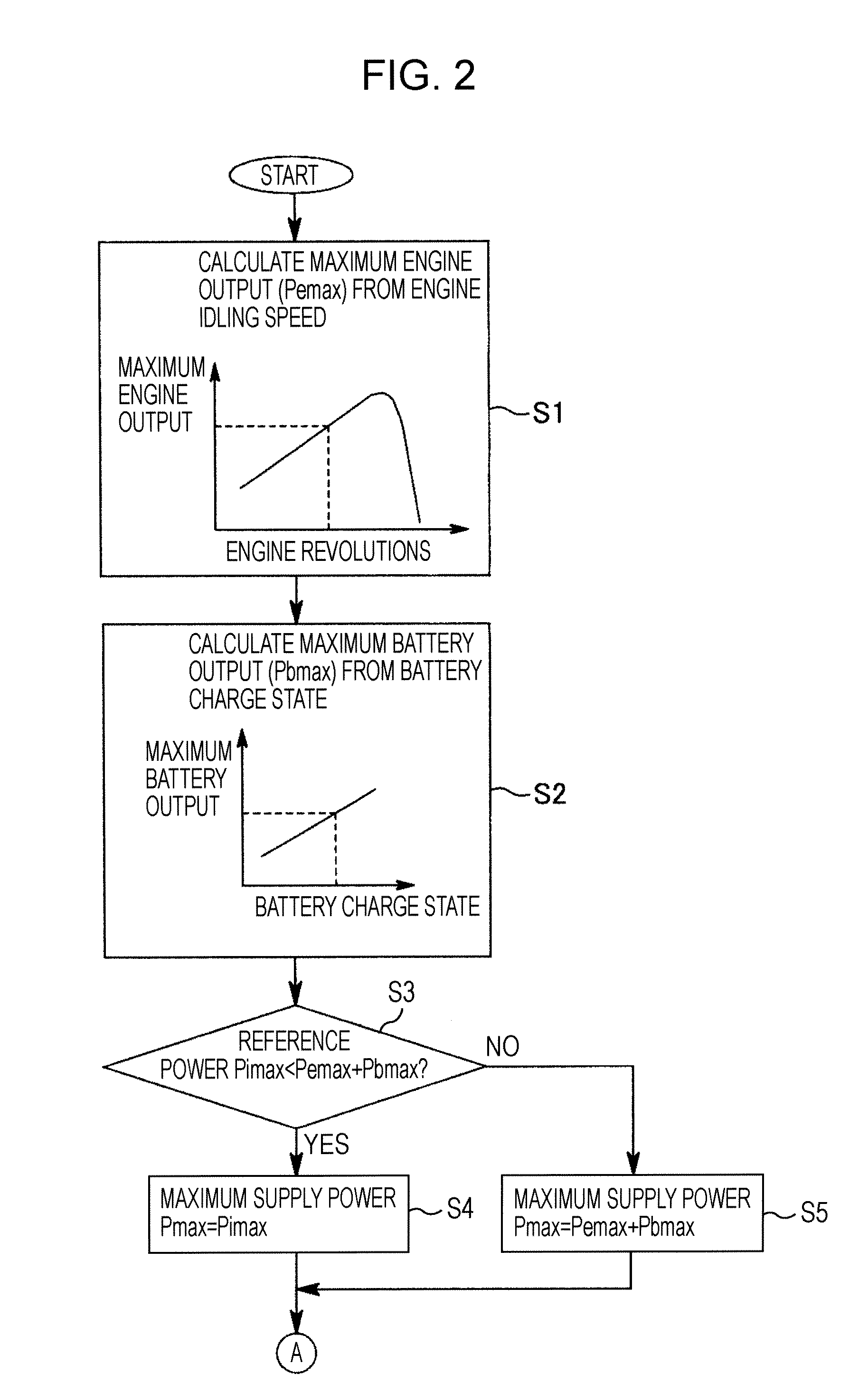
[0057]FIG. 5 and FIG. 6 are flowcharts illustrating operation of the second embodiment. Steps S11 to S15 of FIG. 5 are the same as steps S1 to S5 of FIG. 2. In the second embodiment, step S16 and step S17 are performed simultaneously with routines of steps S11 to S15. In step S16, a hydraulic pump tilt calculation value qtmp (cc / rev) under normal control is calculated from hydraulic actuator operation signals, pump pressure, and the like (corresponding to step S9 of FIG. 3). In step S17, a speed instruction value Ns under normal control is calculated from a rotating operation signal and the like.

[0058]Subsequently, in step S18 of FIG. 6, on the basis of the amount of operation of each actuator, a ratio between the sum of the amounts of operation of the hydraulic actuators and the amount of operation of the rotation motor 1...

third embodiment

See FIG. 7

[0061]In the third embodiment of the present invention, a maximum hydraulic pump output and a maximum rotation motor output are determined according to an operation pattern, not according to the amount of operation. Hereinafter, only differences from the second embodiment will be described with reference to FIG. 5 and FIG. 6.

[0062]After steps S11 to S17 of FIG. 5, in a step corresponding to step S18 of FIG. 6, a maximum hydraulic pump output and a maximum rotation motor output are determined on the basis of a hydraulic pump output power ratio Rp and a rotation motor output power ratio Rs which are preset, as shown in FIG. 7, in relation to operation patterns of the actuators.

[0063]For example, in operation pattern 9 in FIG. 7, if boom operation, arm operation, and rotating operation are simultaneously performed, the hydraulic pump output power ratio Rp and the rotation motor output power ratio Rs are 67% (2 / 3) and 33% (1 / 3), respectively. According to these ratios, the max...


PUM


Abstract

In a hybrid excavator, a hydraulic pump and a generator motor are connected in parallel to an output shaft of an engine and a rotation motor is driven by a battery. The generator motor assists the engine by performing a motor function. Power consumption of each of the hydraulic pump and the rotation motor is detected. The output of the hydraulic pump and the rotation motor is controlled such that the sum of the detected power consumption does not exceed maximum supply power set as the sum of power that can be supplied to the hydraulic pump and the rotation motor.

Description

BACKGROUND OF THE INVENTION[0001]1. Field of the Invention[0002]The present invention relates to a hybrid construction machine which uses both engine power and electric power.[0003]2. Description of the Related Art[0004]Known techniques relating to the present invention will be described. Here, an excavator will be described for illustrative purposes.[0005]As illustrated in FIG. 8, an excavator includes a crawler-type lower traveling structure 1 and an upper rotating structure 2 rotatably mounted on the lower traveling structure 1. A working attachment 3 is mounted on the upper rotating structure 2. The working attachment 3 includes a boom 4 capable of moving up and down, an arm 5 attached to an end of the boom 4, a bucket 6 attached to an end of the arm 5, and cylinders 7, 8, and 9 which are hydraulic actuators for driving the boom 4, the arm 5, and the bucket 6, respectively.[0006]If the excavator is a hydraulic excavator, a hydraulic motor is used as a rotation actuator for rotat...

Claims


Application Information

Patent Timeline
Patent Type & Authority Patents(United States)
IPC IPC(8): F16D31/02
CPCB60K6/46B60L11/123B60W10/08B60W10/30B60L1/003Y02T10/7077B60L2240/421B60L2240/423B60L2240/441B60L2240/486B60W20/00B60W2510/0638B60W2510/081B60W2510/083B60W2510/244B60W2540/16B60W2710/081B60Y2200/25Y02T10/6217Y02T10/642B60L50/61Y02T10/62Y02T10/64Y02T10/70B60W20/10B60W2300/17Y02T10/7072
Inventor KOMIYAMA, MASAYUKIKAGOSHIMA, MASAYUKI
Owner KOBELCO CONSTR MASCH CO LTD
Why Eureka
Try Eureka