Heat dissipating module

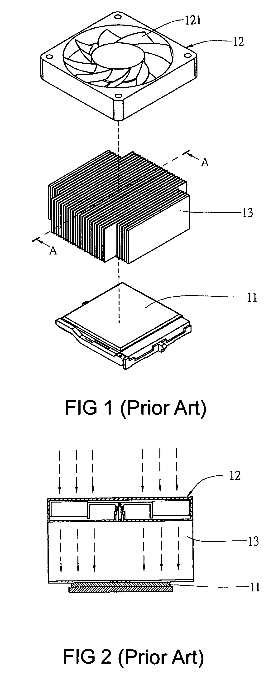
a heat dissipation module and module technology, applied in the direction of air-flow influencers, marine propulsion, vessel construction, etc., can solve the problems that the axial flow fan b>12/b> performs undesirable heat dissipation for the cpu

Active Publication Date: 2010-03-02
ASIA VITAL COMPONENTS SHENZHEN CO LTD
View PDF12 Cites 11 Cited by
  • Summary
  • Abstract
  • Description
  • Claims
  • Application Information

AI Technical Summary

Benefits of technology

[0009]A further object of the present invention is to provide a heat dissipating module, which is capable of gathering the air to cool the heat dissipated object.

Problems solved by technology

However, the conventional axial flow fan 12 is usually mounted to right top of the CPU 11 and no air flows at the center of the axial flow fan 12 such that the axial flow fan 12 performs undesirable effect of heat dissipation for the CPU 11.

Method used


Image

  • Heat dissipating module
  • Heat dissipating module
  • Heat dissipating module

Examples


Embodiment Construction

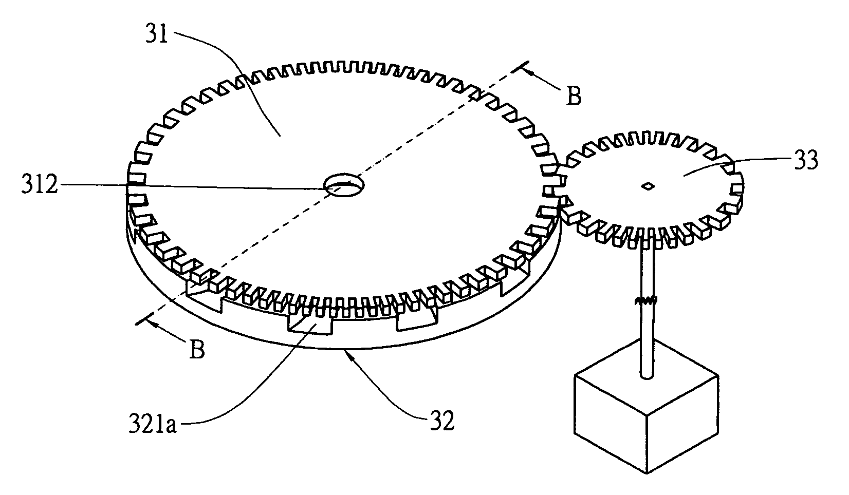
[0024]Referring to FIGS. 5 to 7, the first embodiment of a heat dissipating module according to the present invention includes a rotational member 31, a stationary member 32 and a driving member 33. The rotational member 31 is coupled to the driving member 33 and an uneven surface 311 is provided at a lateral side of the rotational member 31 as shown in FIG. 7A and the stationary member 32 is disposed to space the uneven surface 311. A plurality of flow passages 321 are provided at the stationary member 32 with an air inlet 321a being disposed at an end of each flow passage 321 and an air outlet 321b being disposed at another end of each flow passage 321.

[0025]It is known that ideal fluid is without viscosity and interruption between adjacent layers is unable to occur. However, the ordinary fluid is viscous such that when the driving member 33 actuates the rotational member 31 to rotate as shown in FIG. 7, the viscosity of the fluid allows the fluid to rotates with the rotational me...


PUM


Abstract

A heat dissipating module includes a rotational member, a stationary member and a driving member. The rotational member meshes with the driving member and has an uneven surface at a side thereof to space to the stationary member. The stationary member has plural flow passages and each flow passage has an air inlet at an end thereof and an air outlet at another end thereof. When the driving member actuates the rotational member to rotate with the fluid, the fluid enters the stationary member via the inlet and gathers at the outlet before being guided outward for concentrating the air and cooling the heat dissipated object.

Description

BACKGROUND OF THE INVENTION[0001]1. Field of the Invention[0002]The present invention is related to a heat dissipating module particularly to a heat dissipating module, which includes a rotational member, a stationary member and a driving member to induce air for cooling heat dissipated object.[0003]2. Brief Description of the Related Art[0004]Currently, the central processing unit (CPU) is forced to dissipate heat with the axial flow fan or a centrifugal fan as shown in FIGS. 1 and 2. The CPU 11 is attached to a radiator 13 and an axial flow fan 12 is attached to the radiator 13. The axial flow fan 12 provides a fan blade section 121 to induce air flowing. Due to the heat generated by the CPU 11 not distributing to the surface thereof evenly, the central position has higher temperature than rest part of the CPU 11. However, the conventional axial flow fan 12 is usually mounted to right top of the CPU 11 and no air flows at the center of the axial flow fan 12 such that the axial flo...

Claims


Application Information

Patent Timeline
Patent Type & Authority Patents(United States)
IPC IPC(8): F01D1/36
CPCF04D25/02F04D25/06F04D29/582H01L23/467H01L2924/0002H01L2924/00
Inventor CHANG, BOR-HAWCHOU, CHU-HSIEN
Owner ASIA VITAL COMPONENTS SHENZHEN CO LTD
Why Eureka
Try Eureka