Low profile anterior thoracic and thoracolumbar plate

a low-profile, anterior thoracic and thoracic plate technology, applied in the field of implantable devices for stabilizing the spine, can solve problems such as pain to patients and affecting the surrounding muscl

Inactive Publication Date: 2010-03-02
ORTHOPAEDIC INT
View PDF18 Cites 6 Cited by
  • Summary
  • Abstract
  • Description
  • Claims
  • Application Information

AI Technical Summary

Problems solved by technology

A disadvantage of rod-based systems is in the distance the device extends outwardly from the vertebrae, potentially affecting the surrounding muscle and causing pain to the patient.

Method used


Image

  • Low profile anterior thoracic and thoracolumbar plate
  • Low profile anterior thoracic and thoracolumbar plate
  • Low profile anterior thoracic and thoracolumbar plate

Examples


Embodiment Construction

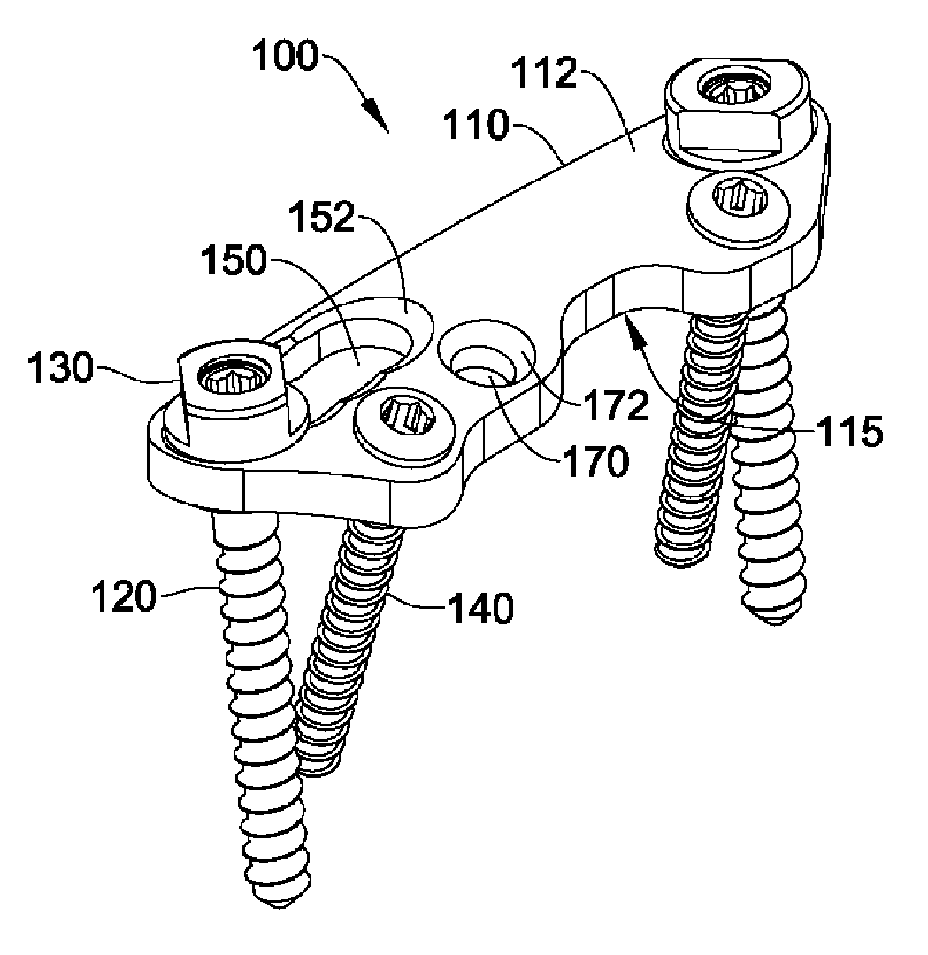
[0020]The current invention is a device for anterior fixation of the spine, particularly the thoracic and thoracolumbar regions. The device includes a plate and a pair of bolts with matching nuts. In some embodiments, the device also includes one or more screws. The device has a low profile due to the design of the nut and the corresponding slot and bolt aperture in the plate. The plate has a single-slot design that minimizes spreading of the slotted portion of the plate when the nut is tightened on the bolt, thereby reducing the stress on the plate. In some embodiments, the plate also incorporates a protrusion to accommodate a screw hole beside the slot while maintaining plate strength and keeping a narrow width in other portions of the plate.

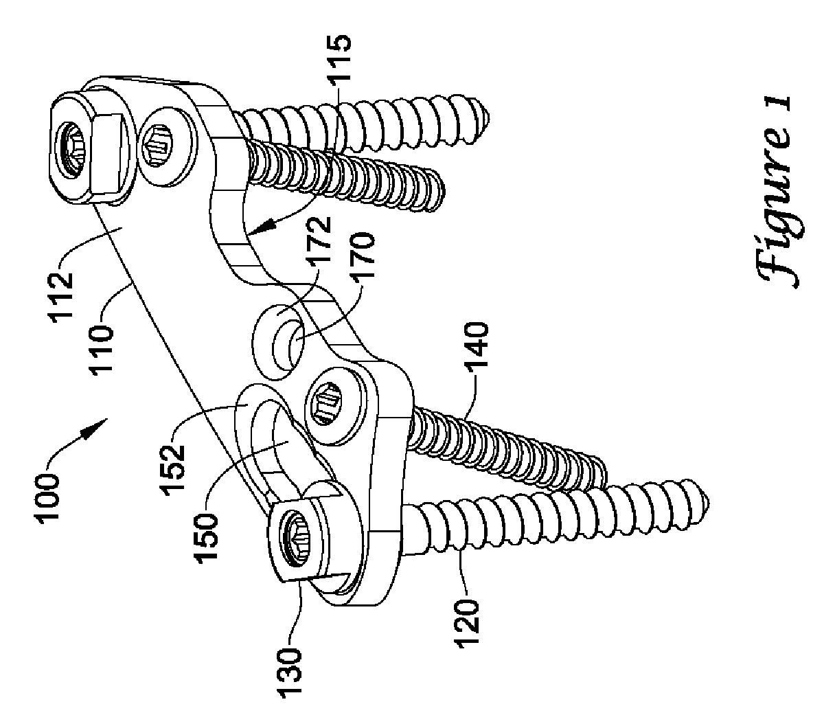
[0021]Referring now to the drawings wherein like reference numerals refer to like elements throughout the several views, FIG. 1 shows a plate assembly 100 according to one embodiment of the invention. The assembly 100 includes an elongated pla...


PUM


Abstract

A spinal implant assembly is provided for stabilizing the spine. The assembly includes an elongated plate, bolts, and nuts. The plate is fixed to vertebrae spanning an injury or deformity to a disc or vertebra using the bolts and nuts. Screws can provide additional stability. The nuts are configured to extend through the plate to clamp the plate between collars on both the bolts and nuts.

Description

FIELD OF THE INVENTION[0001]The present invention pertains to implantable devices for stabilizing the spine. In particular, the invention relates to a plate-based system for anterior internal fixation of the spine.BACKGROUND OF THE INVENTION[0002]The general use of either rods or plates fixed to the vertebrae above and below a defect such as a fracture, ruptured disc, tumor, or deformity, is known, especially in the thoracic and thoracolumbar spine. The system disclosed in U.S. Pat. No. 5,603,714 uses rods to connect screws threaded into each vertebra spanning the defect. The advantage of a rod-based system is its flexibility to accommodate different indications using the same basic components. A disadvantage of rod-based systems is in the distance the device extends outwardly from the vertebrae, potentially affecting the surrounding muscle and causing pain to the patient.[0003]A plate-based system can have a lower profile than a rod-based system. The application technique for a pla...

Claims


Application Information

Patent Timeline
Patent Type & Authority Patents(United States)
IPC IPC(8): A61B17/80A61B17/56A61B17/70
CPCA61B17/7007A61B17/701A61B17/7058A61B17/7059A61B17/7011
Inventor CATBAGAN, ADRIANSASING, JUDE L.MORALES, AGUSTIN G.PAISO, JOSE MARTIN S.MADERA, EDWIN C.BAJO, JEFFREY B.GUSTILO, RAMON B.
Owner ORTHOPAEDIC INT
Why Eureka
Try Eureka